7
UniSyn Universal Audio to Synth Interface User’s Manual
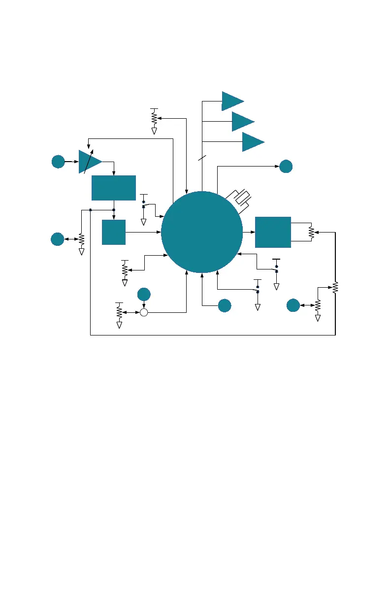
Block Diagram of UniSyn Audio to Synth Interface
16/80/160Hz
16/80/160Hz
HPF
HPF
IN
IN
PRE
PRE
OUT
OUT
STM32F
STM32F
303CB uC
303CB uC
0-50dB
0-50dB
FM
FM
+
SQR/
SAW
SIN
SYNTH
SYNTH
OUT
OUT
6kHz
6kHz
LPF
LPF
-2 to +2
octaves
semitone
steps
XLR/TRS
COMBO
24.576MHz
GATE
THRESH
MIDI
MIDI
OUT
OUT
USART TX
SQR/SAW
3
PITCH CV
PITCH CV
ENV CV
ENV CV
GATE CV
GATE CV
CS4334
CS4334
STEREO
STEREO
DAC
DAC
VCF
FREQ
VCF MOD/
MIDI BEND
MODE
SUSTAIN
SUSTAIN
PEDAL
PEDAL
3:1
COMP
HARMONY
The block diagram helps to understand the signal ow inside the
UniSyn. First the AGC is applied to the input signal, boosng it by
a gain from 0-50dB to achieve the opmum preamp output level.
The AGC preamp is followed by a switchable high-pass lter (HPF).
The HPF output drives the preamp output and is the “Source”
signal that gets mixed together with the internal synth signal.
The HPF is followed by a xed 6kHz low-pass lter (LPF), whose
output goes into one of the ADC inputs of the STM32F303CB
microcontroller (uC). The uC generates PITCH, ENV, GATE CV and
MIDI outputs and drives a CS4334 stereo DAC to generate the sine
and square/sawtooth waves. Various inputs to the uC control
gate threshold, 3:1 compression, sustain, VCF frequency, harmony,
MIDI bend mode, and square/saw waveform selecon.
 Loading...