B
Benjamin WestJul 30, 2025
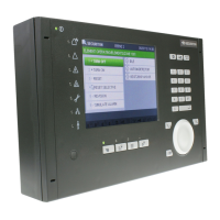
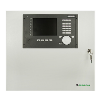
What to do if Securiton SecuriFire 1000 Control Panel shows a contaminated detector?
- LLauren JohnsonJul 30, 2025
If your Securiton Control Panel indicates a contaminated detector, first, press the Lists button, then select the WARNINGS entry, and press Enter. The contaminated detector list will be displayed, allowing you to browse with the SecuriWheel. You can print this list by pressing PRINT REPEAT on the internal protocol printer. Note that contaminated detectors must be replaced. In user level 3 (password entry required), detector contaminations can be reset.