2
The SEL-710 offers flexibility in tailoring I/O to your specific application. The SEL-710 has six rear-panel slots, labeled
as Slots A, B, C, D, E, and Z. Slots A, B, and Z are base unit slots, each associated with a specific function. Optional
digital/analog I/O cards are available for the SEL-710 in Slots C, D, and E. Optional communications cards are available
only for Slot C, an RTD card is available only for Slot D, ac voltage or ac voltages and differential current cards are
available only on Slot E, and current cards are available for Slot Z. The previous figure and table show the slot allocations
for the cards.
Because installations differ substantially, the SEL-710 offers a variety of card configurations that provide options for an
array of applications. Choose the combination of option cards most suited for your application.
Dangers, Warnings, and Cautions
Card Installation for Slots C, D, E, and Z
Perform the following procedure to install or replace any one of the cards into Slots C, D, E, or Z of the base unit:
1. Save the settings and event report data before installing the new card in the relay.
2. Remove the power supply voltage
q from terminals A01+ and A02–, and then remove the ground wire
from the green ground screw.
3. Disconnect all the connection plugs.
4. Remove the eight screws on the rear
i and remove the rear cover.
5. Remove the plastic filler plate covering the slot associated with the card being installed.
6. Insert the card in the correct slot.
Make sure the contact fingers on the printed circuit board are bent at an approximate 130-degree angle
relative to the board for proper electromagnetic interference protection.
7. Before reattaching the rear cover, check for and remove any foreign material that may remain inside the
SEL-710 case.
8. Carefully reattach the rear cover.
9. Reinstall the eight screws that secure the rear cover to the case
i.
SELECT 8 DI
b
SELECT 4 ACI
a
Refer to the SEL-710 MOT for power supply and CPU board variants.
b
The fast, high-current interrupting output option and the 8 DI card option require R300 or higher firmware revisions.
c
Requires R201 or higher firmware revisions.
d
Requires R306, R402, or higher firmware revisions.
Disconnect or de-energize all
external connections before
opening this device. Contact with
hazardous voltages and currents
inside this device can cause
electrical shock resulting in injury
or death.
Have only qualified personnel
service this equipment. If you are
not qualified to service this
equipment, you can injure
yourself or others, or cause
equipment damage.
To install an option card, the relay
must be de-energized and then
re-energized. When re-energized,
the relay will reboot. Therefore,
de-energize the protected
equipment before installing the
option card to prevent damage to
the equipment.
Equipment components are
sensitive to electrostatic
discharge (ESD). Undetectable
permanent damage can result if
you do not use proper ESD
procedures. Ground yourself, your
work surface, and this equipment
before removing any cover from
this equipment. If your facility is
not equipped to work with these
components, contact SEL about
returning this device and related
SEL equipment for service.
Refer to the Model Option Table on the SEL website for ordering details.
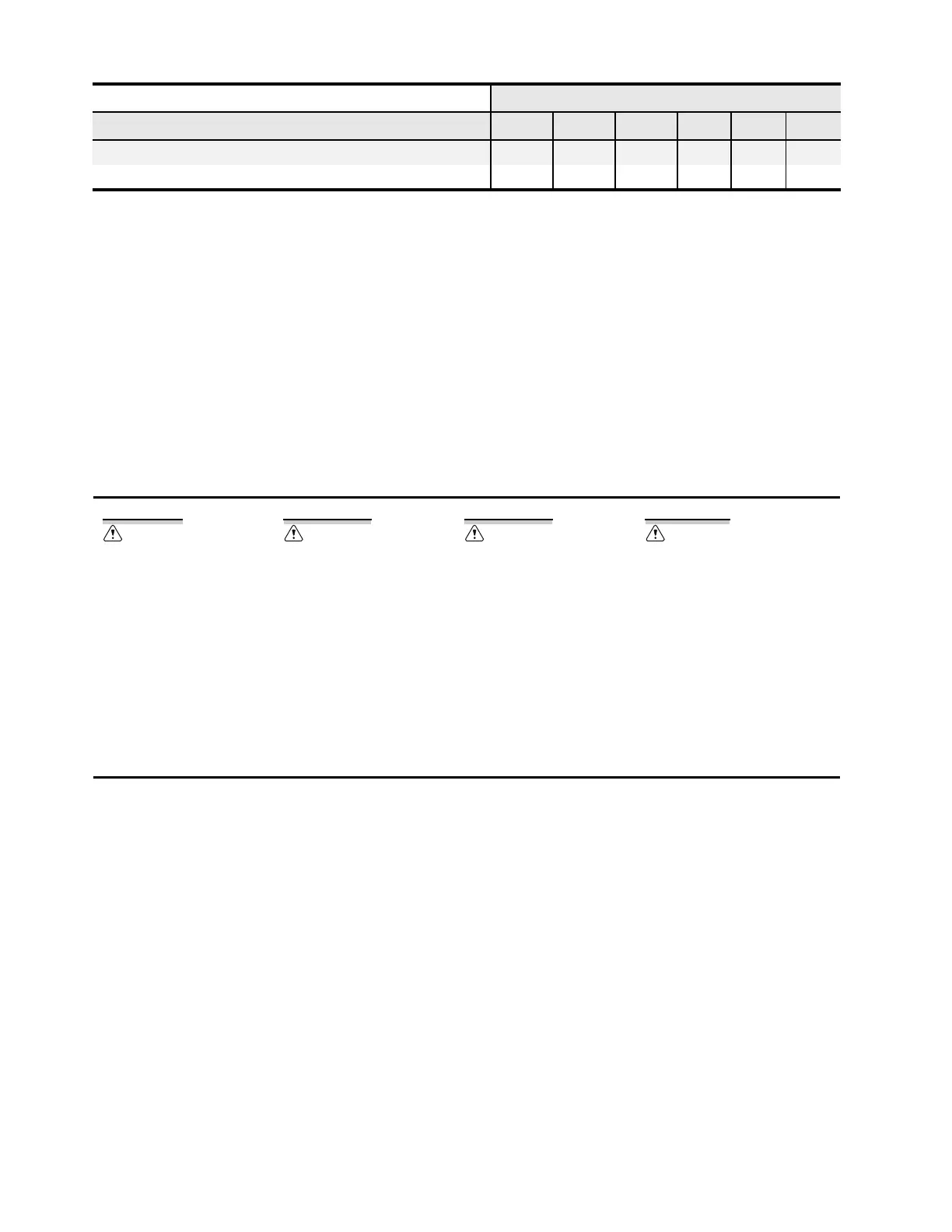
Card Slot Options
Card Type A B C D E Z
 Loading...