ST 402 ‘CAYMAN’ NLJD
27
3 16-segment led gauge of reection levels white 3
4 Power-on led indicator red POWER
5 SEARCH mode indicator yellow SEARCH
6 AUDIO mode indicator yellow AUDIO
7 5-segment tuning bar* yellow TUNING
8 socket for power-and-control cable CONTROL
9 USB port USB
* the TUNING segment bar has two functions:
– in the SEARCH mode, it shows the selected sensitivity of the receiver (SEN)
– in the AUDIO mode, it shows the selected frequency combination (CH 1..5)
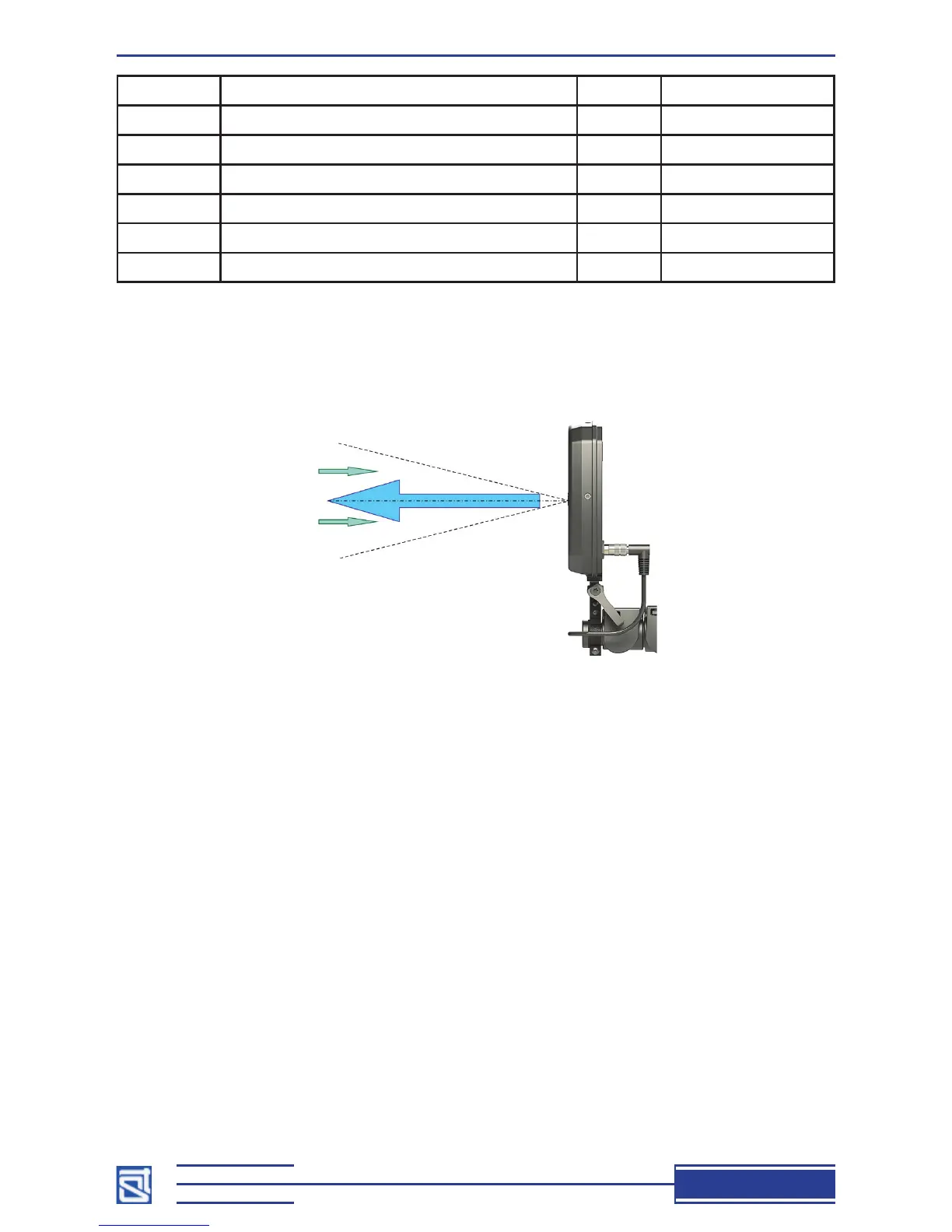
The boresight directions of the receiving and transmitting antennas are shown in Fig. 5.
Fig. 5
1.6.2. Main Unit
The main unit of ST 40
2 Cayman is housed in a durable plastic body (2, Fig. 2) fitted on top
with a handle (5, Fig. 2) with three control buttons (15, Fig. 2). It has a battery compartment (3,
Fig. 2) for two type 18650 accumulator batteries, closed with a metal cap (4, Fig. 2). On the left
side of the main unit are a headphone socket (11, Fig. 2) and a power-and-volume knob (12,
Fig.2), and on the right side there is a shield bearing the name of the device, its serial number,
and the name of its manufacturer company (13, Fig. 2). Also on the right, a speaker grid can be
found (14, Fig. 2).
The main unit’s body hosts electronics controlling the device. For durability’s sake, all the
components of the main unit are assembled on a single bearing structure made of metal, while the
plastic body only serves protective and aesthetic purposes.
1.6.3. Telescopic Arm
The four-section telescopic arm is used to bring the antenna up close to remote objects under
inspection. Its length can be adjusted with the aid of cam clamps (9, Fig. 2).
Its base section is anchored inside the main unit. The fore section of the rod is tted with
a bracket mount for the antenna module (6, Fig. 2). A lever handle (7, Fig. 2) is used to x the
antenna in a desired position.