0.01
0.1
1
10
Ø
Ø
Ø
User programmable CT primary and CT secondary.
Memory retention.
Potential free Pulse output for energy.
DISPLAY
BURDEN
MEASUREMENT
segment LED display, Height 0.5”
3Ø 4wire,3Ø-3wire,2Ø-3wireand
1Ø-2wiresystem
11to300VAC(L-N);
19to519VAC(L-L)InstallationCategory
45-65Hz
Nominal5A AC(Min-11mA,Max-6A)
1A/ 5A to 10,000A(Programmable for anyValue)
1Ato 10,000A if CT secondary is 1 else CT
primary is 5Ato 10,000A
1A or5A (programmable)
Class 1
230V AC, 20%, 50 / 60Hz
Voltagerange:External 4VDCmax.
Currentcapacity:100mA max
100ms 50ms.
1000pulses/kWh
6 digit 7
0.5 VA@5A per phase
kWh (resettable)
WIRING INPUT
RATEDINPUTVOLTAGE
FREQUENCY RANGE
RATEDINPUTCURRENT
CT PRIMARY
Note :
CTSECONDARY
ACCURACY
AUXILIARYSUPPLY RANGE
OUTPUT
PulseOutput
PulseWidth :
INT :
-
±
±
III
: 2
selec
EM306A
OperatingInstructions
FEATURES
SPECIFICATIONS
ENVIRONMENTAL CONDITIONS
MOUNTING
WEIGHT
-Indooruse
-Altitudeofupto2000meters
-Pollutiondegree
Temperature: Operating:-10to55 C
Storage:-20to75 C
Humidity : Upto85%RH,non-condensing
Panelmounting
340gms
II
O
O
96x96
MECHANICALINSTALLATION
Outline
Dimensions(inmm)
Panelcutout
Dimensions
(inmm)
90.5
99
99
5
50
91.5
91.5
N
S2S1S2S1S2S1
V1
N
L
O
A
D
I1
V2 V3
L1
L2
L3
I2 I3
PULSEO/P
L
N
+
CONNECTIONSDIAGRAM
TERMINALCONNECTIONS
EM306A
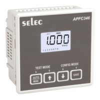
FRONTPANELDESCRIPTION
OP348-V01
EM306A
PRG
selec
INT
kWh
REV
x10
1000
Impulse
/kWh
CONFIGURATION
Thereare4dedicatedkeyswithsymbolsmarkedas,
,,.Usethese4keystoenterintoconfiguration
menu/changesetting.
Thesettingsshouldbedonebyaprofessional
aftergoingthroughthisusersmanualandafterhaving
understoodtheapplicationsituation.
Fortheconfigurationsettingmode:
Note: ,
! Use()and()keysfor3sec.toenterorexitfrom
configurationmenu.
Use()and()keysforincreasinganddecreasing
parametersvaluerespectively.
Use ()keytogobacktopreviouspage.
Use ()keytosavethesettingandmoveonnextpage.
!
!
!
Function
Rangeor
Selection
Config
page.
Factory
Setting
Password
ChangePassword
NewPassword
NetworkSelection
CT Secondary
CT Primary
10
10
No
3P4W
1
1.1
2
3
4
5
5
0000to9998
No/Yes
3P3W/3P4W
1A or5A
1A,5A to
10,000A (10.0kA)
0000to9998
Forresettingenergyparametersuserwillbepromptedfor
password.Ifcorrectpasswordisentered,theuserwillbeableto
resetallenergyparameters.Thispasswordwillbevaluewhich
willbegreaterthantheconfigurationpasswordby1.
FactoryDefault
ResetEnergy
Password
ResetActiveEnergy
5.02
5
5.1
5.01
11
No
No
No
No/Yes
No/Yes
0001To9999
No/Yes
<15
<150
<1500
£ 2000
Pulseoutput
(kWh/pulse)
CTRatio
kWh
0.01
0.1
1
10
RESOLUTION:
SAFETYPRECAUTIONS
All safety related codifications, symbols and
instructions that appear in this operating manual or on
the equipment must be strictly followed to ensure the
safety of the operating personnel as well as the
instrument.
If the equipment is not used in a manner specified by the
manufacturer it might impair the protection provided by the
equipment.
Do not use the equipment if there is any mechanical
damage.
Ensure that the equipment is supplied with correct
voltage.
1. Read complete instructions prior to installation and
operation of the unit.
2. Risk of electric shock.
3. The equipment in its installed state must not come in close
proximity to any heating sources, steam, caustic vapors,
oils or other unwanted process by products.
1. This equipment, being built-in-type, normally becomes a
part of main control panel and in such case the terminals do
not remain accessible to the end user after installation and
internal wiring.
2. Conductors must not come in contact with the internal
circuitry of the equipment or else it may lead to a safety
hazard that may in turn endanger life or cause electrical
shock to the operator.
3. Circuit breaker or mains switch must be installed
between power source and supply terminals to facilitate
power ‘ON' or ‘OFF’ function. However this switch or
breaker must be installed in a convenient position normally
accessible to the operator.
4.
5. The equipment shall not be installed in environmental
conditions other than those mentioned in this manual.
. The equipment does not have a built-in-type fuse.
Installation of external fuse of rating 275V AC / Amp for
electrical circuitry is highly recommended.
Before disconnecting the secondary of the external current
transformer from the equipment, make sure that the current
transformer is short circuited to avoid risk of electrical
shock and injury.
6
0.5
/ battery
INSTALLATIONGUIDELINES
1. To prevent the risk of electric shock, power supply to the
equipment must be kept OFF while doing the wiring
arrangement.
2. Wiring shall be done strictly according to the terminal
layout. Confirm that all connections are correct.
3. Useluggedterminals.
4. To reduce electromagnetic interference use of wires with
adequate ratings and twists of the same in equal size shall
be made with shortest connections.
5. Layout of connecting cables shall be away from any
internal EMI source.
6. Cable used for connection to power source, must have
a cross section of 1.5mm . These wires shall have
currentcarryingcapacity of 6A.
7. Before attempting work on device, ensure absence of
voltages using appropriate voltage detection device.
2
(AWG 15)
WIRINGGUIDELINES
CAUTION:
WARNING :
CAUTION:
For installing the meter
1. Prepare the panel cutout with proper dimensions s shown
below.
a
2 meter. Push the meter into the panel cutout. Secure the in
its place by fitting the clamp on the rear side. fit clamps on
both sides in diagonally opposite location for optimum
fitting.
3. For proper sealing, tighten the screws evenly with required
torque.
Terminal screw tightening torque 0.5 -m
Screw clamp tightening torque : 0.1 -m
: N (4.42536 Lb-inch)
N (0.885 Lb-inch)
MAINTENANCE
1. The equipment should be cleaned regularly to avoid
blockageofventilatingparts.
2. Cleantheequipmentwithacleandryordampcloth.
Donotuse anycleaningagentotherthanwater.
INT : The INT LED provides optical output for calibration
verification as well as visual indication of energy
integration. The pulse rate is 1000 Pulses/kWh.
X10 : X10 LED ON when the resolution is 10. It is the
indication of count reading which must be multiplied by
10togetactualkWhconsumed.
REV : REV LED gives the indication of reversal of two
or more CT connections presence of
In such cases meter may not
indicate the correct energy consumption. The CT shoul
be connectedtothe meterwithcorrectpolarities
or negative power
in any or all phases.
d
.
USERGUIDE
LEDINDICATIONS
Doc.name:OP INST EM306A OP348-V01(Page1of2)