selec
OperatingInstructions
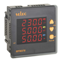
MFM376SERIES
OP506-V02
SPECIFICATIONS
96x96
InstallationCategory III
Frequency
ActivePower
Apparentpower
PowerFactor
ActiveEnergy
ReactiveEnergy
ApparentEnergy
Measurement
Accuracy
VoltageV
L-N
VoltageV
L-L
±0.5%ofFullscale
± Fullscale0.5%of
Current
±0.5%ofFullscale
±0.1%
For L-NVoltage >20V,
For L-L Voltage >35V
±0.01
Class1
Class1
Class1
ReactivePower
1%
1%
1%
ACCURACY
Product
ORDERCODEINFORMATION
Supply
Certification
LISTED
DISPLAY
T
Note :
CT SECONDARY
PT PRIMARY
PT SECONDARY
DISPLAYUPDATE TIME
DISPLAYSCROLLING
POWER CONSUMPTION
ENVIRONMENTAL CONDITIONS
MOUNTING :
WEIGHT
OUTPUT
Pulse Output
Pulse Width :
3 Row of 4 Digits
7 Segment LED Display 0.49 inch Height Digit
Integrated with parameter Units
3 Ø 4 wire, 3 Ø - 3 wire, 2 Ø - 3 wire and Ø -
Installation Category (600V)
1Ato 10,000Aif CT secondary is 1 else
5Ato 10,000A
1Aor 5A(programmable)
100V to 500kV (Programmable for any value)
100 to 500V (Programmable for any value)
1 sec. for all parameters
Auto / Manual / Default
Less than 8VA
- Indoor use
- Altitude of up to 2000 meters
- Pollution degree
Temperature :
Humidity : Up to 85% non-condensing
Panel mounting
MFM376-230V AC : 260gms
MFM376-C : 230gms
Voltage range : External 24V DC max.
Current capacity :100 mAmax
100ms 5ms.
WIRING INPU
RATED INPUT VOLTAGE
FREQUENCY RANGE
RATED INPUT CURRENT
BURDEN
CT PRIMARY
- 1 2 wire
(R/Y/B Programmable)
45-65 Hz
Nominal 5AAC (Min-14mA, Max-6A)
0.5VA@5Aper phase
1A/ 5Ato 10,000A(Programmable for anyvalue)
11 to 300V AC (L-N) ; 19 to 519V AC (L-L)
III
II
:
±
Operating : -10 C to 55 C
Storage : -20 C to 75 C
° °
° °
240VAC, 20%,50/60Hz±
MFM376-230VAC
Note: a)Forvoltage,currentandpowerresolutionis
automaticallyadjusted
b)Forpowerfactorresolutionis0.001
c) • Blinksindicatingaccumulationofenergy,ifload
isconnectedonanyonephaseof3Phase.
0.01K
0.1K
1K
0.01M
0.1M
<40
<400
< 0040
< 00040
< 000040
0.001K
0.01K
0.1K
1K
0.01M
PT
x
Ratio
CTRatio
Pulse
INT
RESOLUTION:
For installing the meter
1. Prepare the panel cutout with proper dimensions s
shown below.
a
2 meter. Push the meter into the panel cutout. Secure the
in its place by fitting the clamp on the rear side. fit
clamps on both sides in diagonally opposite location for
optimum fitting.
3. For proper sealing, tighten the screws evenly with
required torque.
MECHANICALINSTALLATION
Outline
Dimensions (inmm)
Panelcutout
Dimensions (inmm)
90.5
99
99
3
49
90.5
90.5
TERMINALCONNECTIONS
MAINTENANCE
1. Theequipmentshouldbecleanedregularlytoavoid
blockageofventilatingparts.
2. Cleantheequipmentwithacleandryordampcloth.
Donotuse anycleaningagentotherthanwater.
SAFETYPRECAUTIONS
All safety related codifications, symbols and
instructions that appear in this operating manual or on
the equipment must be strictly followed to ensure the
safety of the operating personnel as well as the
instrument.
If the equipment is not used in a manner specified by the
manufacturer it might impair the protection provided by the
equipment.
Do not use the equipment if there is any mechanical
damage.
Ensure that the equipment is supplied with correct
voltage.
1. Read complete instructions prior to installation and
operation of the unit.
2.Riskofelectricshock.
3. The equipment in its installed state must not come in
close proximity to any heating sources, oils, steam,
caustic vapors or other unwanted process by products.
1. To prevent the risk of electric shock, power supply to the
equipment must be kept OFF while doing the wiring
arrangement.
2. Wiring shall be done strictly according to the terminal
layout. Confirm that all connections are correct.
3. Use lugged terminals.
4. To reduce electromagnetic interference use of wires with
adequate ratings and twists of the same in equal size shall
be made with shortest connections.
5. Layout of connecting cables shall be away from any
internal EMI source.
6. Cable used for connection to power source, must have a
cross section of 0.5mm to 2.5mm
Thesewires shall have current carryingcapacity of 6A.
7. Copper cable should be used
8. Before attempting work on device, ensure absence of
voltages using appropriate voltage detection device.
2 2
( 20 to 14AWG ; 75 C(min)).
(Stranded or Single core cable).
0
WIRINGGUIDELINES
1. This equipment, being built-in-type, normally becomes a
part of main control panel and in such case the terminals
do not remain accessible to the end user after installation
and internal wiring.
2. Conductors must not come in contact with the internal
circuitry of the equipment or else it may lead to a safety
hazard that may in turn endanger life or cause electrical
shock to the operator.
3. Circuit breaker or mains switch must be installed
between power source and supply terminals to facilitate
power 'ON' or ‘OFF’ function. However this switch or
breaker must be installed in a convenient position
normally accessible to the operator.
4.
5. The equipment shall not be installed in environmental
conditions other than those mentioned in this manual.
. The equipment does not have a built-in-type fuse.
Installation of external fuse of rating 275V AC / Amp for
electrical circuitry is highly recommended.
Before disconnecting the secondary of the external
current transformer from the equipment, make sure that
the current transformer is short circuited to avoid risk of
electrical shock and injury.
6
0.5
/ battery
INSTALLATIONGUIDELINES
CAUTION:
WARNING :
CAUTION:
N
S2S1S2S1S2S1
V1
N
L
O
A
D
I1
V2 V3
L1
L2
L3
I2 I3
PULSE
OUTPUT
L
N
+
CONNECTIONDIAGRAM
0.01K
0.1K
1K
0.01M
0.1M
1M
0.1M
4000000
1M
kWh/
kVAh/
kVArh
40V-270VDC,
85V-270VAC,50/60Hz
MFM376-C
MFM376-230VAC
MFM376-C
N
S2S1S2S1S2S1
V1
N
L
O
A
D
I1
V2 V3
L1
L2
L3
I2 I3
PULSE
OUTPUT
+
+
+
CONNECTIONDIAGRAM
RS485
Doc.name:OP INST MFM376SERIESOP506-V02(Page1of4)