6. VENT LOCATION AND ENCLOSURES
SELKIRK TYPE B GAS VENTS ARE RECOMMENDED TO BE INSTALLED WITHIN THE HEATED
PORTION
OF THE STRUCTURE WHENEVER POSSIBLE TO REDUCE HEAT LOSS WHICH MAY IN TURN
LEAD
TO POOR DRAFT AND/ OR CONDENSATION/ ICING PROBLEMS.
If an exterior location is necessary, Selkirk Type B Gas Vent must be:
- Enclosed by a chase spaced out 2” from the vent at least to the roof line.
- The enclosure should be caulked to prevent entry of moisture.
- It is also recmommended that
the chase be insulated up to a
maximum of R-12 (RSI 2.1).
- Exposed insulation shall be of
the rigid type. Non rigid type
must be supported so that the
insulation does not come in
contact with the vent.
- The bottom of the enclosure
must be closed off.
- It is recommended to provide
an access panel for future
inspection and cleaning.
Appliances served by an
exterior gas vent must have an
air supply to the appliance room
adequate to balance indoor and
outdoor pressures. Otherwise,
“stack action” of the heated
building can cause reverse
venting action when the
appliance is off, or operating on
its pilot.
In multi-family residential, high
rise and many other types of
buildings, codes specify that
vents must be located in fire-
rated shafts or chases. Building
code requirements in such cases
must be carefully followed with respect to wall construction, access,
clearance, support, initial penetration of breaching, and method of termination.
7. FIRE STOPPING
All Type B Gas Vents passing through floors, ceilings or walls must be
firestopped using 26 gauge or heavier galvanized steel. (See Fig. 5 and 6)
The fire stop must close the area between the outer wall of the pipe and the
opening in the structure. In areas such as attics with no floor, the fire stop
should be placed on top of a properly framed opening. KEEP WIRES AND
INSULATION OUT OF REQUIRED AIR SPACE AROUND GAS VENT.
Fire stops may be used as vent pipe supports. See Section 10. For gas vents
within a shaft or chase, firestopping is provided by the vertical walls of the
shaft. Any openings in the chase/ shaft below the roof must be firestopped.
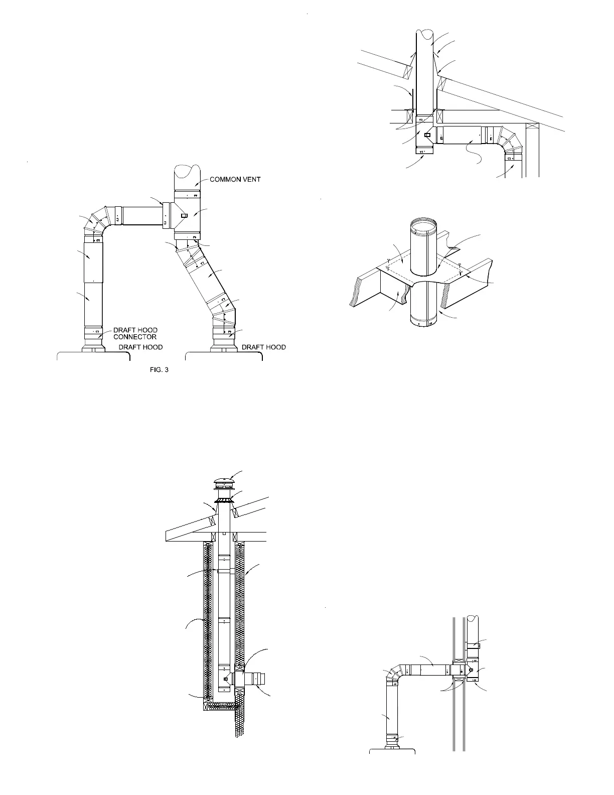
8. USE OF GAS VENT FITTINGS (See Figs. 3 & 7.)
Do not cut gas vent pipe or fittings. Adjustable lengths are telescoped over
fixed lengths, to accommodate odd distances between vent lengths or
connectors. An adjustable length suspended below a support serves as an
expansion joint between two fixed points of properly supported gas vent.
Ordinarily, the adjustable length must be secured, but for expansion joints it
should just maintain good contact and a minimum 1-1/2” overlap. DO NOT USE
adjustable lengths to suspend any weight of pipe below.
Model RV Elbows are fully adjustable.
Selkirk tees, elbows, increasers, and short lengths are specially designed to
facilitate interconnections.
Tees used to start vertical vents must use a tee cap to prevent air leakage. All
unused openings in a gas vent must be sealed to prevent loss of effective
vent action.
5. VENT CONNECTOR TYPE AND SIZE
Selkirk Gas Vent pipe meets all building code and safety standards for use as
gas appliance vent connectors. Correct selection of connector and vent size
is detailed in the Selkirk Gas Vent and Chimney Sizing Handbook, the Installation
Gas Code CSA-B149.1-00, the National Fuel Gas Code NFPA 54, and local/
regional codes.
Draft hood connectors must be attached to the appliance outlet with screws.
Single wall connectors, if used must be secured to the appliance, to the gas
vent, and at all joints with 3 sheet metal screws per joint. Attachment of vent to
non-metallic outlets should be per appliance manufacturer recommendations.
LENGTH
TYPE B VENT
TYPE B VENT
DRAFT HOOD
CONNECTOR
45/60° ELBOW
INCREASER
45/60° ELBOW
INCREASER
90° ELBOW
ADJUSTABLE
TEE
the Canadian Fuel Gas Code CSA-B149.1-00, the National Fuel Gas Code
NFPA 54, and/ or local building codes for air supply requirements.
Enclose completely or use
metal shield (by others).
Maintain at least minimum
airspace clearance to
enclosure, wires, and
building insulation.
FIG. 5 - TYPICAL CEILING AND ROOF PENETRATIONS
Tee Cap
Firestop
Tee
Pipe
Adjustable
Length
Pipe
Adjustable
Flashing
(Attic)
Storm
Collar
Maintain minimum airspace
clearance to combustibles,
wires, and insulation.
1" - for 3" thru 24" sizes
2" - for 26" thru 48" sizes
at Walls, Ceiling, Roof, and
Penetrations.
FIG. 6
FIRE STOPPING REQUIRED FOR ALL
CEILING/FLOOR PENETRATIONS
Framing
required if
no floor
Maintain minimum airspace
clearance to combustibles,
wires, and insulation.
1" - for 3" thru 24" sizes
2" - for 26" thru 48" sizes
at Walls, Ceiling, Roof, and
Penetrations.
Gas Vent
Fire Stop placed
on top of floor or
framed opening.
Hole in any generic
firestop / support
plate to be nominal
pipe ID + 5/8". (Ex.-
hole for 4" vent to
be 4-5/8")
26 gauge galv.
steel Fire stop
Rain Cap
Storm Collar
Wall
Support/Band
R12 Max
Insulation
Enclosure
2” Clearance
Wall
Drafthood
Connector
Vented Flashing
Wall
Thimble
FIG. 4 - EXTERIOR
ENCLOSED WALL
PENETRATION FOR
TYPE B
Tee Cap
(Must be
used here)
LENGTH
ADJUSTABLE
90° ELBOW
TYPE B VENT
CONNECTOR
DRAFT HOOD
TEE
Wall Support/Band
Assembly For Sizes
3"-8". Support Plate
or Bucket for sizes
26"-48"
Pipe Collars or
Wall Thimbles for
3"-8" Supplied by
others for larger
sizes.
FIG. 7 - INTERIOR WALL PENETRATION FOR TYPE B
FIRESTOP SPACER
OR
WALL THIMBLE
 Loading...