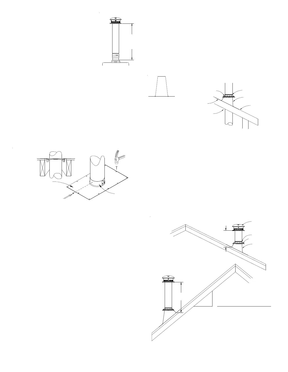
FIG. 9 FIRESTOP/SUPPORT ASSEMBLY
Plate support may be
trimmed or replaced
with custom size,
generic plate if
necessary, as long as
proper clearances are
established and
maintained.
CLAMPING
BAND
Top and sides of
flashing under roofing
Bottom of flashing
over roofing
Adjustable
Flashing (AF)
Apply Silicone
Sealant
Storm Collar (SC)
Maintain airspace
minimum clearance to
combustibles through roof.
1" - for 3" thru 24" sizes
2" - for 26" thru 48" sizes
FIG. 11-B
ELEMENTS FOR PROPER ROOF FLASHING INSTALLATION
FIG. 11-A
TALL CONE FLASHING
FOR FLAT ROOFS ONLY
Minimum Height
From Roof
To Lowest Discharge
Over 20/12 to 21/12
FIG. 12-B
LOCATION RULES FOR FLAT TO 21/12 PITCH
Height
above
roof
Roof Pitch is X/12
12
Over 10/12 to 11/12
Over 18/12 to 20/12
Over 16/12 to 18/12
Over 14/12 to 16/12
Over 12/12 to 14/12
Over 11/12 to 12/12
Over 9/12 to 10/12
Over 8/12 to 9/12
Over 7/12 to 8/12
Flat to 7/12
Roof Pitch
X
FIG. 12-A
FOR ROOF PITCH OF 7/12 OR LESS
8.0
3.25
6.0
7.5
7.0
5.0
4.0
Opening Ft.
1.5
2.5
2.0
1.0
Storm Collar (SC)
Adjustable
Flashing (AF)
Silicone Sealant
Round Top
12"
Minimum
distance to
roof
Insure 1” minimum airspace is established and maintained.
Should an offset be required use a CF roof support or a support plate to
support the vent above the offset. Offsets can be a maximum of 60 degrees
and may take place in the attic.
Plumbers strap may be used to support both horizontal and vertical piping. All
gas vents extending above the roof more than 5 feet must be securely guyed
or braced.
11. FLASHING
The roof opening should be located and sized such that the vent is vertical
and has the required air space clearance. The Tall Cone Flashing is for flat
roofs only. It is nailed in place through all four sides of the base flange. The
Adjustable Roof Flashing is positioned with the lower portion of the base
flange over roofing material and the upper portion of the base flange under
the roofing material. Nail through only the upper portion and sides of the base
flange. (DO NOT nail through lower flange.) Use nails with a neoprene washer,
or cover the nail heads with a silicone sealant. Finish roofing around the
flashing, covering the sides and upper areas of the flange with roofing
material. See Figures 10-A & B.
Rule II - Tops for gas vent sizes 14” and larger.
For installations other than covered by the table (Fig. 11-B), or closer than 8
feet to any vertical wall, the top shall be not less than 2 feet above the highest
point where the vent passes through the roof and at least 2 feet higher than
any portion of a building within 10 feet.
These rules were established on the basis of tests conducted in accordance
with American National Standard ANSI/UL 441.
12. VENT TERMINATION
Gas vent piping must extend through the flashing to a height above the roof
determined by Rules shown below. A storm collar is installed on the vent pipe
over the opening between pipe and flashing. Silicone sealant is used over the
joint between pipe and storm collar. Install a Selkirk Round Top to keep out rain
and snow.
If the gas vent extending more than 1.25m (4’) above the roof additional lateral
support is required such as a Selkirk Roof Brace Kit.
Rule 1:
The top is suitable for installation on listed gas vents terminating a sufficient
distance from the roof so that no discharge opening is less than 2 feet
horizontally from the roof surface, and the lowest discharge opening will be
no closer than the minimum height specified in Fig. 11-B. These minimum
heights may be used provided that the vent is not less than 8 feet from any
vertical wall.
9. MINIMUM GAS VENT HEIGHT
A minimum gas vent height of 5 feet above the
appliance draft hood is required. Where the vent
has an offset, or serves multiple appliances, greater
heights may be required for proper venting. Special
care must be taken with short gas vents on duct
furnaces, unit heaters, and furnaces in attics to
assure they have sufficient vent height to assure
complete venting. Refer to appliance manufacturer
instructions and local codes for required minimum
heights.
10. SUPPORT - PRIMARY AND OFFSETS
Gas vent piping must be securely supported.
Lateral runs are to be supported at least every 5
feet. The Support Plate has been tested to support a maximum of 10 m (35’)
of Gas Vent; if additional height is required, use another Support Plate on
another floor level. Vertical runs firestopped at 8 to 10 foot intervals need
only be supported near the bottom.
Cut away and frame a four sided opening in the floor from which the Gas
Vent shall be supported, to provide 25mm (1”) minimum clearance to
combustibles.
Nail Support Plate securely to joist and framing members using 4 x 1-1/2” long
nails (1 nail at each corner).
Insert the first length from above through the Band and the opening to achieve
the required amount of Gas Vent below the Support Plate. Secure clamping
band to the length with tabs and 1/4” screws (provided) so weight of vent
rests on plate. Room should be left for the draft hood connector and adjustable
length.
Additional Gas Vent Lengths above the Support are simply stacked on. See
joining section to secure lengths together.
Minumu
vertical
height
5 feet
FIG. 8 - MINIMUM
VERTICAL HEIGHT
10-A
10-B
11-A
11-B
 Loading...