8
WALL SUPPORT (AWS) - 2-1/2" only
As previously mentioned, the ideal location for your chimney system
is within the building envelope. A Wall Support installation is
required when the above mentioned location is not possible.
To complete a proper Wall Support installation, the following parts
may be required:
- Adjustable Wall Support (AWS): Intended for a through-the-wall
installation where the chimney has a horizontal connection. The
AWS is adjustable only from 2" to 2-1/2" from the vertical wall.
NOTE: The AWS is supplied in the Wall Support Kit. For greater
adjustment, the WS must be ordered separately.
Stove Pipe Adaptor (ASE): Transition from chimney to connector.
- Roof Flashing Assembly: Required when the chimney penetrates
a roof or a roof overhang.
- Rafter Radiation Shield (RRS): Required when the chimney is
enclosed immediately below the roof.
- Wall Band (WB): Required to provide lateral support to the chimney.
- Suitable lengths of chimney: The chimney diameter should be sized
to suit the appliance.
-Wall Thimble (WT): Required to pass through a combustible wall.
- Universal Shielding Insulation (JUSI): To reduce cold air infiltration
into the dwelling when installed in conjunction with the Wall
Thimble.
- Rain Cap: To prevent rain and/or debris from entering in the chimney.
Standard or Deluxe model.
The Adjustable Wall Support will support up to 33 ft.
(10 m) of chimney, all of which must be above the support, with the
exception of the 1 foot chimney section
and/or an Insulated Tee Plug,
which is installed below the support.
If the total chimney height exceeds the Adjustable Wall Support
limitation, an Adjustable Intermediate Wall Support (AIWS) must be
installed. See the AIWS section for more details.
Wall Support Installation
Rain Cap
Storm Collar
Wall Band
Locking Band
Insulated Tee
Wall Support
1 Foot Chimney Section
and/or
Insulated Tee Plug
3" Minimum
Chimney Section
Stove Pipe Adapter
Wall Thimble
Inner Half
Wall Thimble
Outer Half
Ventilated Flashing
8 Feet
(Max)
FIGURE 8
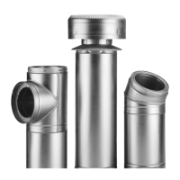
Tee Plug
Female Coupler
(Down)
FIGURE 10
Nut
Side Bracket
Side Bracket
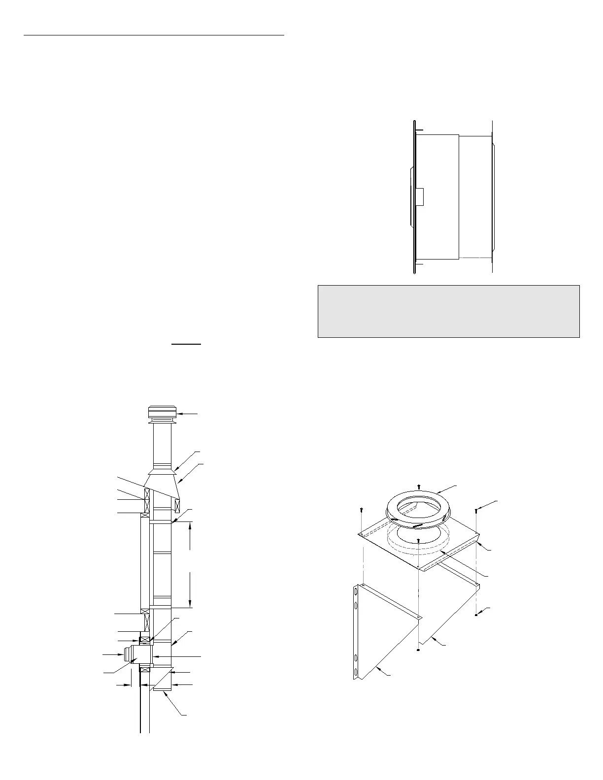
Install the inner half (with round plate) of the Wall Thimble in the inside
wall surface, ensuring that the shield slides over the shield of the outer
half. Once in place and flush against the wall, install the trim plate and
fasten in place with appropriate fasteners through the four pre-punched
holes (see Figure 9).
Assemble the Wall Support (Figure 10) by attaching the 2 side brackets
(point of triangle facing down) to the support plate with the hardware
supplied. Ensure that the female coupler attached to the underside of
the support plate is facing down. For an ajustment of the support plate,
align the fixed holes on the support plate with the elongated holes on
the side brackets.
Adapter Ring
Bolt
Support Plate
Determine the center line of the horizontal connection (length through
the wall) and frame an opening to the dimensions specified in the
Framing Dimension Table 1. (For non-combustible walls (concrete
block or poured foundation), cut a hole 3/16" greater than the outside
diameter of the chimney). Install the outer half (with square plate) of
the Wall Thimble in the outside wall surface. Secure in place using
appropriate fasteners using all of the pre-punched holes.
Telescoping adjustment
from 4-1/2" to 8-3/4"
Interior Inner Half
of Wall Thimble
Black Finishing
Round Plate
Exterior Outer Half
of Wall Thimble
FIGURE 9
Wall Thimble
NOTE: To reduce cold air infiltration into the dwelling you
can install the optional Universal Shielding Insulation (JUSI)
into the Wall Thimble. See separate installation instructions
packaged with the JUSI.
Install an appropriate Insulated Chimney Length such as a one foot
section (or longer if required - not to exceed 24 inch) to the horizontal
branch of the Insulated Tee. Lock securely into the tee branch by
twisting clockwise. A Locking Band must then be installed at this
connection. Make sure the nut and bolt are facing down to prevent
any water from collecting in the locking band.The Tee branch exten-
sion must protrude a minimum of 3" (75 mm) into the room (Fig. 8).