TB-6123 Revision 10/06
Page 3 of 12
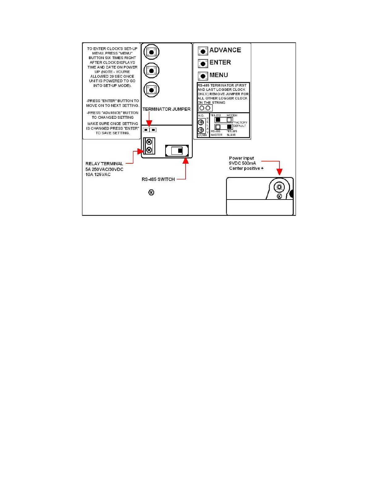
1. Configuration of Clocks Setting, Mounting and Cable Connection
Figure 1. Back Side of SmartlogX
3
™
A. Clocks Baud Rate, ID, Parity, Daylight Option and Port expand
Referring to Figure 1.
1. Plug the 120 volt AC power supply into the unit and then to the appropriate AC source.
Refer to Figure 1. to locate power input jack. The SmartLogX
3
™ will cycle through a self
diagnostic program. The time and date will appear on the screen when the diagnostics is
completed. Step 2 should not be performed until this is completed.
NOTE: If any of the below settings are not correct, press the Advance button
until the correct value appears on the display.
2. From the end of the self diagnosis, press the Menu button six times only (you’re giving a
20 sec limit to do so, or clock will need to be reset by disconnecting power adapter to re-
enter set-up menu). Refer to Figure 1 for Button locations.
3. Baud Rate should be set at 9600 (factory default). Press Enter for the next screen.
4. Parity should be set for ODD (factory default). Press Enter for next screen.
5. The SmartLogX
3
™ ID is a 2 digit field with valid I.D. number 00 through 63. Each
SmartLogX
3
™ should have a different I.D.# if on the same communication line. The
SmartLogX
3
™ should be numbered sequentially starting with 00, so that automatic
polling in the software will not be interrupted.
6. The Daylight Option is to enable daylight savings in the clock.
 Loading...