ENGLISH
Pag. 11
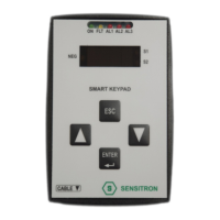
3. Menu
The calibration keypad has a menu with several options, each one of them allows to per-
form dierent actions on the detector. In the following table are summarised all the possible
actions.
Table 2) Calibration keypad menu description
Displayed
name
Meaning Description
PSd Password 1234. It allows to access the keypad menu, otherwise the user
can only reset the detector or visualise its rmware version.
To modify the alarm thresholds and the hysteresis value, the
password is 5345.
ZEro Zero When the detector is turned on for the rst time, or when
a new kit sensor head is mounted into the instrument, the
ZERO calibration is recommended.
This action has to be done under the following two condi-
tions:
-The detector is to be in fresh air (without any gas or interfe-
ring compounds);
-it must be powered on at least for 8 hours.
Span Span The Span allows the instrument calibration and is to be exe-
cuted if the response in gas of the instrument is not correct.
To run the Span calibration, it is essential the use of a sample
gas bottle with Target Gas.
If the concentration of the sample gas bottle is dierent from
that displayed on the keypad, then must be performed the
Span calibration. Otherwise this step is not necessary.
For the correct calibration of gas detectors, Sensitron makes
available a dedicated calibration case complete with all ne-
cessary tools to perform accurate tests. The calibration KIT,
supplied with a carrying case, comprises the necessary in-
strumentation to verify in situ the response of Sensitron's
gas detectors.
The calibration cap can be tted on all of Sensitron sensing
heads by employing, when necessary, the endowed adap-
tors. Both gaskets and screw threads inside the cap allow an
optimum tightness between the sensing head and the cap.
The analysis chamber inside the calibration cap has been de-
signed and realized to obtain a test method identical to the
one adopted in our Laboratory for the initial factory calibra-
tion. The ow meter valve is to be mounted on the gas can
to allow the gas ow at a controlled velocity to obtain accu-
rate data to verify the sensing element status.
t4.20 4-20 cali-
bration
4-20 mA output calibration
 Loading...