ENGLISH
Pag. 6
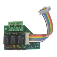
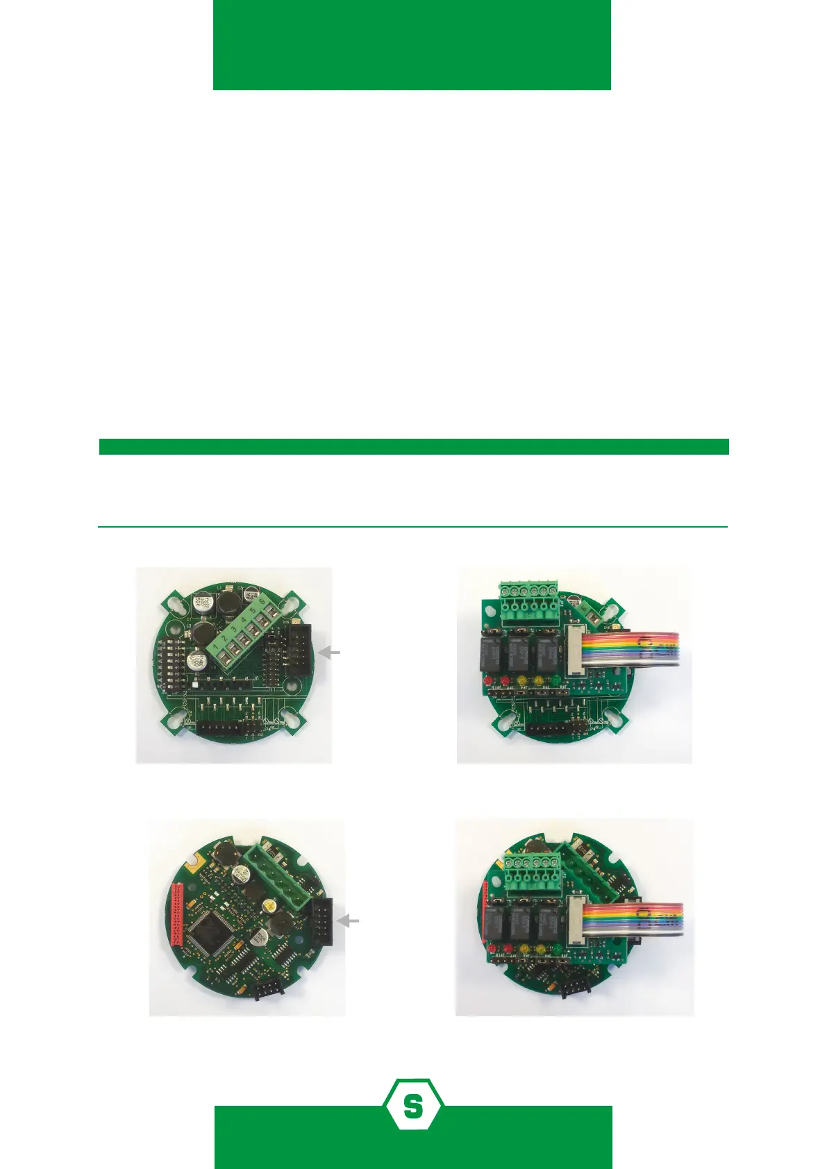
Figure 1) Assembly of the relay card on the SMART3G main board
Figure 2) Assembly of the relay card on the SMARTS main board
3. Assembly
1. Verify the detector has been disconnected before mounting the STS3REL.
2. Insert the supports into the holes on the PCB.
3. Insert the female connector at the edge of the at cable into the male connector on
the main PCB of the detector (see gure 1 and 2 below). Beware that the black triangle
on the female connector (corresponding to pin one) is facing towards the internal part
of the PCB.
4. Tighten the card to the supports with the screws of the relay card.
5. Once the card has been properly mounted the terminal block shall be faced towards
the upper part of the detector, i.e. towards the detector terminal block.
6. The detector can now be wired, connected and powered on.
For the SMART3G’s series detectors, in order to properly activate the ST.S3REL card, it is man-
datory to open the jumper JP5-6 on the detector’s main PCB (refer to the SMART3G’s detec-
tor manual).
IMPORTANT!