The board is powered by a 12vDC current. With no external devices (readers, locks, alarms, etc.) attached,
the board’s consumption is 120mA maximum (IC500) or 370mA maximum (IC500IP). The maximum con-
sumption allowed through the 5V terminals on terminal blocks J1 and J2 is 150 ma.
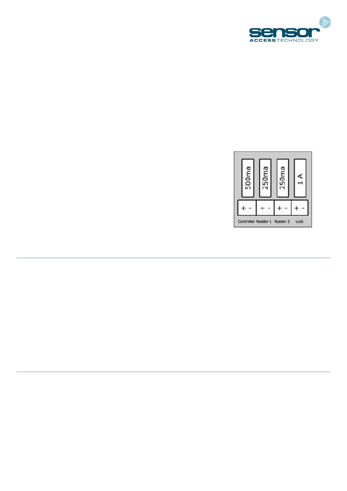
When supplied in Sensor’s Power Supply Unit (E2) you are given 4 independent outputs:
POWER SOURCES AND BOARD CONSUMPTION
- 2 x 12V/250ma terminals - for powering the card/fob readers
- 1 x 12V/1A terminals - for powering the electric door locks
- 1 x 12V/500ma terminal - for powering the controller
See the E-Series Instruction Sheet for further details on the PSU cabinet:
http://public.sensoraccess.co.uk/GuardPointPro/Manuals/hardware/E-SeriesInstructionSheet.pdf
CONNECTING THE READERS
The IC500 controllers can recognise almost any kind of reader technology the use of switches 6, 7 and 8 on
the dipswitch bank DS1. However for the vast majority of installations dipswitch 6 should be set to ON and
switches 7 & 8 set to OFF (Wiegand with parity check). Each reader comes complete with a length of cable
attached. However, there may be times when you want to extend this cable further. In these situations it is
important to select the correct type.
Sensor recommend Belden 9421 for Proximity/Keypad readers and Belden 8458 for Biometric
readers
CONNECTING AN INPUT
A magnetic contact, passive infra-red unit, request to exit switch or any other form of contact can be con-
nected to and monitored via the IC500. As standard, input I3 is configured to allow connection of Request to
Exit (REX) and I1 configured for the connection of a Door monitoring contact.
Sensor recommend any 22AWG, 2 conductor cable
3