8
CONNECTING THE IC500IP (TCP/IP Port)
The IC500IP controller is supplied with a TCP/IP socket on board, allowing it to be assigned an IP address and
so added to a TCP/IP network. In order to connect the IC500 plug one end of a standard RJ45 network cable
into the socket, and the other either into your router/hub or directly into the Ethernet socket on a PC; the
controller will then appear on the network. Before it can be used the controller must be configured via the
application DS Manager (available on the GuardPoint Pro disc, or for free download from the Sensor web-
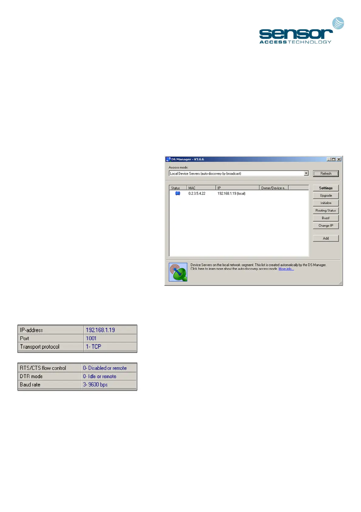
To configure the controller, please go to Start,
Programs, Tibbo, DS Manager. A window
such as that on the right will now appear.
In the main panel of the window will be a list
of all currently detected TCP/IP controllers.
It is almost certainly the case that your IC500
is new and so has a default IP address. This
along with some other settings will need to be
changed.
Click on the visible TCP/IP controller to select
it then click on the Settings button at the top
of the window to bring up the configuration
window.
There are a series of tabs running across the top of the window. Using the tabs you will need to locate the
following settings and change them:
IP-address This should be a unique address
Port This should be set to ‘1001’
Transport Protocol This should be set to ‘1-TCP’
RTS/CTS flow control This should be ‘0-Disabled or remote’
DTR mode This should be ‘0-Idle or remote’
Baud rate This should be set to ‘3-9600 bps’
Once changed, click Ok to return to the main window. The IC500 is now configured and its status icon – rep-
resented by the blue plug to the left - should be solid and clear (as in the screenshot).
The controller is now ready to communicate with the software. For full details on establishing communica-
tion, please refer to the GuardPoint Pro / Pro Lite manual.