EasyManua.ls Logo

Sensor Switch CM 9 WR - User Manual

Sensor Switch CM 9 WR
2 pages
Print Icon
To Next Page IconTo Next Page
Loading...
Sensor Switch 900 Northrop Road, Wallingford, CT 06492 Phone: 1.800.PASSIVE sensorswitch.com ©2014 Acuity Brands Lighting, Inc. All rights reserved 09/19/14 IS-CM-WR-003
1 of 2
Wireless Battery Powered
Sensor Instructions
PASSIVE INFRARED (PIR) & DUAL TECHNOLOGY (PDT)
MODEL NUMBERS
CM 9 WR: Passive Infrared (PIR) Detection - Small Motion 360º
CM 10 WR: Passive Infrared (PIR) Detection - Large Motion 360º
CM PDT 9 WR: Dual Tech (PIR + Microphonics
TM
) Detection - Small Motion 360º
CM PDT 10 WR: Dual Tech (PIR + Microphonics
TM
) Detection - Large Motion 360º
SPECIFICATIONS
SIZE: 4.5” Diameter (11.56 cm)
2.39” Deep (6.07 cm)
WEIGHT: 6 oz
MOUNTING: Ceiling Surface
3.5” Octagon Box
Single Gang Handy Box
COLOR: White
SILICONE FREE / ROHS COMPLIANT
WIRELESS FREQUENCY: 902 MHz (RDT™)
OPERATING TEMP
Standard: -4º to 122º F (-20º to 50º C)
Dual Tech (PDT): 25º to 122º F (-4º to 50º C)
RELATIVE HUMIDITY:
20 to 75% non-condensing
EXPECTED BATTERY LIFE:
~10 years (at factory defaults)
BATTERY TYPE: AA Lithium 1.5V, 3000 mAH
Note: Using replacement batteries
with capacity of <3000 mAh will result in
shorter battery life.
0 ft
9
0 m
2.7
28 21 14 7 0 ft 7 14 21 28
8.5 6.4 4.3 2.1 0 m 2.1 4.3 6.4 8.5
SIDE VIEW
TOP VIEW
28
14
0 ft
14
28
8.5
4.3
0 m
4.3
8.5
0 ft
9
0 m
2.7
28 21 14 7 0 ft 7 14 21 28
8.5 6.4 4.3 2.1 0 m 2.1 4.3 6.4 8.5
SIDE VIEW
TOP VIEW
28
14
0 ft
14
28
8.5
4.3
0 m
4.3
8.5
• Large motion (e.g. walking) detection in a 360º coverage pattern around sensor
• Provides 24 ft (7.32 m) radial coverage when mounted to standard 9 ft (2.74 m) ceiling
• 7 to 15 ft (2.13 to 4.57 m) mounting heights provide 16 to 36 ft (4.88 to 10.97 m) radial coverage
• Passive Dual Technology (also called Microphonics) provides overlapping detection of sounds from human activity
over the complete PIR coverage area. Advanced ltering is utilized to prevent non-occupant noises from keeping the
lights on.
LARGE MOTION 360º model #s: CM 10 WR / CM PDT 10 WR)
Note: Sensor’s screw axis
is oset 7.5º from a long
detection segment
COVERAGE PATTERNS
0 ft
9
0 m
2.7
SIDE VIEW
TOP VIEW
12
6
0 ft
6
12
3.7
1.8
0 m
1.8
3.7
12 6 0 ft 6 12
3.7 1.8 0 m 1.8 3.7
SMALL MOTION 360º model #s: CM 9 WR / CM PDT 9 WR)
Note: Sensor’s screw axis is
aligned with a long detection
segment
0 ft
9
0 m
2.7
SIDE VIEW
TOP VIEW
12
6
0 ft
6
12
3.7
1.8
0 m
1.8
3.7
12 6 0 ft 6 12
3.7 1.8 0 m 1.8 3.7
• Small motion (e.g. hand movements) and large motion detection in a 360º coverage pattern around sensor
• Provides 12 ft (3.66 m) radial coverage when mounted to standard 9 ft (2.74 m) ceiling
• 8 to 15 ft (2.44 to 4.57 m) mounting heights provide 10 to 20 ft (3.05 to 6.10 m) radial coverage
• Passive Dual Technology (also called Microphonics) provides overlapping detection of sounds from human activity
over the complete PIR coverage area. Advanced ltering is utilized to prevent non-occupant noises from keeping the
lights on.
1. Screw battery extension ring to ceiling
using included pointed tip screws (qty 2)
2. Install batteries (qty 2)
INSTALLATION INSTRUCTIONS
3. Plug battery connector cable
into back of sensor
4. Screw sensor to battery extension ring
using included at tipped screws (qty 2)
AA Lithium
AA Lithium
Note: Install decorative sensor lid by pushing up and rotating clockwise.
Note: A low battery status warning is indicated by paired SPODMR WR
switches/load controllers. See switch instructions for details.
Scan QR code to access
video demonstrations:
EXAMPLE APPLICATION DIAGRAM
ON
OFF
LOAD
Line Powered Wireless Switch
& Load Controller
Battery Powered
Wireless Sensor(s)
(Model #: SPODMR WR)
H
GND
(Model #: CM xx WR)
BLK
BLK
WIRELESS RANGE GUIDELINES
Line of Sight: >100 ft (31 m); e.g. corridor
Plasterboard / Dry Wood: 98 ft (30 m), max 5 walls
Concrete Walls / Ceiling: 32 ft (10 m), max 1 wall/ceiling
http://bit.ly/1aszSqd
Note: Avoid locating a Dual Tech sensor in close proximity to the switch, as the sound of the relay could trigger the sensor back on. If the load always cycles immediately back on after
turning o, the problem can be remedied by: 1) moving the sensor further from the SPODMR WR, or 2) setting the Occupancy Time Delay to value 14, which will disable the microphone.
Question and Answer IconNeed help?

Do you have a question about the Sensor Switch CM 9 WR and is the answer not in the manual?

Summary

Specifications

Model Numbers

Lists available models for Passive Infrared (PIR) and Dual Technology (PDT) sensors.

Coverage Patterns

Small Motion 360° Coverage

Details small motion detection patterns and radial coverage for sensors.

Large Motion 360° Coverage

Details large motion detection patterns and radial coverage for sensors.

Installation Instructions

Wireless Range Guidelines

Pairing Instructions

Setup Instructions

Switch Learn Mode (Pairing Mode)

Explains how to enter switch learn mode to add remote devices.

Sensor Teach Mode

Describes the sensor state for transmitting its ID to facilitate pairing.

Operational Modes

Details selection of Auto-On, Manual-On, or Predictive w/ Expiration modes.

Occupancy Time Delay

Sets the duration the relay remains closed after last occupied transmission.

Sensor Test Mode

Temporarily sets Occupancy Time Delay to 10 seconds for testing.

Additional Settings & Modes

Heartbeat Settings

Configures the frequency for transmitting sensor status information.

Microphone Enable;Disable

Enables or disables the microphone for Dual Tech sensors.

Unlearn (Unpair)

Removes paired devices from the switch unit's learned list.

Microphone Setback Time

Sets maximum duration microphone detections keep lights on.

Sensor Reset

Resets the sensor to its original factory default settings.

Switch Diagnostic;Reset;Unlearn All

Provides options for resetting, unlearning devices, and status counts.

Switch Status LED Operation

Controls the normal operation of the switch unit's button LEDs.

Overview

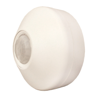
The device is a Wireless Battery Powered Sensor, offering both Passive Infrared (PIR) and Dual Technology (PDT) for occupancy detection. It is designed for ceiling surface mounting and can be installed in a 3.5" octagon box or a single gang handy box. The sensor is white, silicone-free, and RoHS compliant, operating on a 902 MHz RDTM wireless frequency.

Technical Specifications:

  • Size: 4.5" Diameter (11.56 cm), 2.39" Deep (6.07 cm)
  • Weight: 6 oz
  • Operating Temperature: Standard models operate from -4° to 122° F (-20° to 50° C). Dual Tech (PDT) models operate from 25° to 122° F (-4° to 50° C).
  • Relative Humidity: 20 to 75% non-condensing.
  • Expected Battery Life: Approximately 10 years (at factory defaults).
  • Battery Type: AA Lithium 1.5V, 3000 mAH. Note that replacement batteries with less than 3000 mAh capacity will result in shorter battery life.

Model Numbers:

  • CM 9 WR: Passive Infrared (PIR) Detection - Small Motion 360°
  • CM 10 WR: Passive Infrared (PIR) Detection - Large Motion 360°
  • CM PDT 9 WR: Dual Tech (PIR + Microphonics™) Detection - Small Motion 360°
  • CM PDT 10 WR: Dual Tech (PIR + Microphonics™) Detection - Large Motion 360°

Coverage Patterns:

The sensor offers two main coverage patterns:

  • Small Motion 360° (CM 9 WR/CM PDT 9 WR):

    • Detects both small (e.g., hand movements) and large motion in a 360° pattern around the sensor.
    • Provides 12 ft (3.66 m) radial coverage when mounted to a standard 9 ft (2.74 m) ceiling.
    • Mounting heights between 8 to 15 ft (2.44 to 4.57 m) provide 10 to 20 ft (3.05 to 6.10 m) radial coverage.
    • Passive Dual Technology (Microphonics™) models provide overlapping detection of sounds from human activity over the PIR coverage area, with advanced filtering to prevent non-occupant noises from keeping lights on.
  • Large Motion 360° (CM 10 WR/CM PDT 10 WR):

    • Detects large motion (e.g., walking) in a 360° pattern around the sensor.
    • Provides 24 ft (7.32 m) radial coverage when mounted to a standard 9 ft (2.74 m) ceiling.
    • Mounting heights between 7 to 15 ft (2.13 to 4.57 m) provide 16 to 36 ft (4.88 to 10.97 m) radial coverage.
    • Passive Dual Technology (Microphonics™) models also provide overlapping detection of sounds from human activity over the PIR coverage area, with advanced filtering to prevent non-occupant noises from keeping lights on.

Installation Instructions:

  1. Screw the battery extension ring to the ceiling using the two included pointed tip screws.
  2. Install the two AA Lithium batteries.
  3. Plug the battery connector cable into the back of the sensor.
  4. Screw the sensor to the battery extension ring using the two included flat-tipped screws.
  5. Install the decorative sensor lid by pushing up and rotating clockwise.

Wireless Range Guidelines:

  • Line of Sight: >100 ft (31 m), e.g., in a corridor.
  • Plasterboard / Dry Wood: 98 ft (30 m), with a maximum of 5 walls.
  • Concrete Walls / Ceiling: 32 ft (10 m), with a maximum of 1 wall/ceiling.

Usage Features (Setup Instructions):

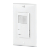
The sensor is designed to be paired with SPODMR WR series wireless switch units. Setup involves using push-buttons on both the sensor and the wall switch.

  • Switch Learn Mode (Pairing Mode):

    1. Press and hold both switch buttons for 3 seconds until button LEDs flash.
    2. Press the switch's ON button 3 times. The switch will then be in "learn mode" and accept teach broadcasts from remote devices.
    3. While in learn mode, the switch's LEDs will rapid flash, then slow blink the number of learned devices.
    4. The unit stays in learn mode for 2 minutes after the last device was learned or until the ON button is pressed.
    5. Each time a new device is learned, the switch will toggle its relay. Wait a minimum of 4 seconds before pairing another device.
  • Sensor Teach Mode:

    1. While the switch is in Learn Mode, press and release the sensor button 2 times.
    2. The sensor's LED will rapid flash when transmitting its ID.
    3. The sensor resumes normal operation after one transmission. This procedure can also be used to unpair a sensor when a switch is in Unlearn mode.
  • Operational Modes: Selectable between Auto-On, Manual-On, or Predictive w/ Expiration.

    1. Press and hold both switch buttons for 3 seconds.
    2. Press the switch's ON button 5 times.
    3. The LED will flash the current setting.
    4. Press the switch's ON button the corresponding number of times to change the setting:
      • 1 - Auto-On: Load turns on when occupied, off when vacant. OFF button turns load off and disables occupancy until ON is pressed.
      • 2 - Manual-On/Vacancy (default for -SA option units): Sensor acts as a vacancy detector. Load turns off after occupancy is no longer detected. Load must be turned on manually by pressing ON. After sensor times out, there's a 10-second grace period for automatic turn-on.
      • 3 - Predictive Mode w/ Expiration (default for non-SA units): Load turns on when occupied, off when vacant. Load can be overridden to off by pressing OFF. If the room remains occupied, load stays off. After room becomes vacant, switch reverts to automatic on/off after Occupancy Time Delay expires.
    5. The switch's LED will flash back the current setting (3 times, then exits).
  • Occupancy Time Delay: Sets the duration a paired SPODMR WR switch's relay remains closed after the last occupied transmission. For PIR sensors, this can be set from the sensor or the switch. For Dual Tech sensors, it must be set from the sensor after pairing.

    1. Press and release the sensor button 4 times.
    2. The LED will flash the current setting (selections 1-13).
    3. Press the sensor button the corresponding number of times to change the setting (from 30 sec to 30 min).
    4. The LED will flash back the new setting (3 times, then exits).
    • Note: The sensor Heartbeat Setting will automatically adjust to match this setting if under 5 minutes, and be set to 5 minutes for any higher setting.
  • Sensor Test Mode: Temporarily sets the Occupancy Time Delay to 10 seconds. The sensor LED flashes every 5 seconds if PIR occupancy is detected.

    1. To Enter (Exit) test mode: Press and release the sensor button 6 times.
    2. Wait until the LED begins to flash back.
    3. Press and release the sensor button twice to Enter test mode (or once to Exit test mode).
    • Note: Test Mode expires automatically after 10 min. Dual Technology (Microphone) detections will not reset the 10-second time delay in Test Mode. While in Test Mode, the sensor Heartbeat Setting is 5 seconds.

Maintenance Features (Additional Settings & Modes):

  • Heartbeat Settings: Controls the frequency the sensor transmits status information.

    1. Press and release the sensor button 3 times.
    2. The LED will flash the current setting (selections 1-3).
    3. Press the sensor button the corresponding number of times to change the setting (from 30 sec to 5.0 min).
    4. The LED will flash back the new setting (3 times, then exits).
    • Note: A Heartbeat Setting shorter than 5 min will reduce battery life. It is recommended to leave the Heartbeat Setting alone as it will automatically adjust with the Occupancy Time Delay.
  • Microphone Enable/Disable (Dual Tech versions only):

    1. Press and release the sensor button 7 times.
    2. The LED will flash the current setting (selections 1-2).
    3. Press the sensor button the corresponding number of times to change the setting (1 - Disable, 2 - Enable*).
    4. The LED will flash back the new setting (3 times, then exits).
  • Unlearn (Unpair): Removes a remote device from the switch's list of learned devices.

    1. Press and hold both switch buttons for 3 seconds.
    2. Press the switch's ON button 4 times.
    3. While in Unlearn Mode, the unit will rapid flash then slow blink the number of learned devices.
    4. The unit stays in Unlearn Mode for 2 minutes, or until one device is unlearned. Press the sensor button 2 times to unlearn (unpair).
    5. Each time a device is unlearned, the switch will toggle its relay.
  • Microphone Setback Time (Dual Tech versions only): Sets the maximum duration that only microphone detections (without PIR detections) will keep the lights on.

    1. Press and release the sensor button 5 times.
    2. The LED will flash the current setting (selections 1-5).
    3. Press the sensor button the corresponding number of times to change the setting (from 15 min to Infinite).
    4. The LED will flash back the new setting (3 times, then exits).
  • Sensor Reset: Returns the sensor to original factory settings.

    1. Press and release the sensor button 9 times.
    2. The LED will flash once.
    3. Press and release the button 2 times.
    4. The LED will flash back twice (3 times, then exits and resets).
  • Switch Diagnostic/Reset/Unlearn All: Provides options to reset and/or unlearn currently paired remote devices, and provides total paired and inactive device count information.

    1. Press and hold both switch buttons for 3 seconds.
    2. Press the switch's ON button 9 times.
    3. The LED will flash the current setting (selections 1-8).
    4. Press the switch's ON button the corresponding number of times to change the setting (e.g., Do nothing*, Reset settings to factory default and unlearn all, Unlearn all paired devices, etc.).
    5. LEDs will flash back the current setting (3 times, then exits).
  • Switch Status LED Operation: Controls the normal operation of the button's LEDs on the switch unit.

    1. Press and hold both switch buttons for 3 seconds.
    2. Press the switch's ON button 11 times.
    3. The LED will flash the current setting (selections 1-2).
    4. Press the switch's ON button the corresponding number of times to change the setting (1 - LEDs enabled*, 2 - LEDs disabled).
    5. The LED will flash back the current setting (3 times, then exits).
    • Note: In disabled mode, LEDs will still flash when the button is pushed, the device is in Learn or Unlearn mode, or flashing back a setting or error code.

Warranty:

The device comes with a 5-year limited warranty. Complete warranty terms are located at www.acuitybrands.com/CustomerResources/Terms_and_conditions.aspx.

Sensor Switch CM 9 WR Specifications

General IconGeneral
BrandSensor Switch
ModelCM 9 WR
CategoryAccessories
LanguageEnglish

Related product manuals