1 of 2
Sensor Switch 900 Northrop Road, Wallingford, CT 06492 Phone: 1.800.PASSIVE sensorswitch.com ©2014 Acuity Brands Lighting, Inc. All rights reserved 01/26/14
IS-WSX-004
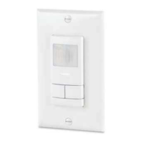
WSX FAMILY
INSTRUCTIONS
PHYSICAL SPECS
SIZE: 2.74”H x 1.68”W x 1.63”D (6.96 cm x 4.27 cm x 4.14 cm)
(not including ground strap)
WEIGHT: 5 oz
MOUNTING: Single Gang Switch Box
MOUNTING HEIGHT: 30-48 in (76.2-121.9 cm)
SILICONE FREE
ROHS COMPLIANT
ELECTRICAL SPECS
MAXIMUM LOAD (Single Phase)
800 W @ 120 VAC
1200 W @ 277 VAC
1500 W @ 347 VAC
MINIMUM LOAD: None
MOTOR LOAD: 1/4 HP
FREQUENCY: 50/60 Hz (timers are 1.2x for 50 Hz)
ENVIRONMENTAL SPECS
OPERATING TEMP
Standard: 14º to 122º F (-10º to 50º C)
LT Option (PIR): -40º to 122º F (-40º to 50º C)
LT Option (PDT): -4º to 122º F (-20º to 50º C)
RELATIVE HUMIDITY:
Standard: 20 to 75% non-condensing
LT Option: 20 to 90% non-condensing
(electronics coated for corrosion resistance)
SPECIFICATIONS
COVERAGE PATTERN
1.2 m
4 ft
Small motion
detection to ~20 ft
Large motion detection to >36 ft
SIDE VIEW
0 18 27 369
ft
0 6 9 123
m
This product is pre-congured for wiring without a neutral; however, if connection to neutral is required by code, the unit easily converts in seconds.
CONVERSION FROM GROUND ONLY NO NEUTRAL TO NEUTRAL WIRING
Step 1:
Remove Yellow
Label
Step 2:
Loosen Screws and
Remove Metal Link
Step 3:
Connect Neutral to
Silver Screw and
Ground to Green Screw
WIRING TO GROUND NO NEUTRAL WIRING TO NEUTRAL
•Small motion (e.g. hand movements) detection up to 20 ft (6.10 m), ~625 ft
2
•Large motion (e.g. walking) detection greater than 36 ft (10.97 m), ~2025 ft
2
•Wall-to-wall PIR coverage
•Units with -PDT (Passive Dual Technology) option
(also called Microphonics) provide overlapping
detection of human activity over the complete
PIR coverage area. Advanced ltering is utilized
to prevent non-occupant noises from keeping
the lights on.
TOP VIEW
BASE MODEL #s
WSX: Passive Infrared (PIR) Detection - Auto On
WSX SA: Passive Infrared (PIR) Detection - Manual On
WSX NL: Passive Infrared (PIR) Detection - Manual On
WSX PDT: Dual Technology (PIR + Microphonics) Detection - Auto On
WSX PDT SA: Dual Technology (PIR + Microphonics) Detection - Manual On
WSX PDT NL: Dual Technology (PIR + Microphonics) Detection - Manual On
10 20
30 36
12 9 6 3 0 m 3 6 9 12
Small
motion
detection
Small
motion
detection
to ~20 ft
6
3
0 m
Small motion ~40 ft coverage
REMOVE MET
AL LINK
IF CONNECTING TO
NEUTRAL
REMOVE MET
AL LINK
IF CONNECTING TO
NEUTRAL
GND
H
N
BLK BLK
BLK
BLK
LOAD
GND
120/277 VAC WIRING
BLACK* - Line Input
BLACK* - Load Output
*BLACK wires
can be reversed
}
WIRE COLOR KEY
347 VAC WIRING (-347 Option)
Red wires replace Black wires.
For additional wiring diagrams, scan QR CODE below or go to:
GND
H N
LOAD
BLK
BLK
REMOVE METAL LINK
IF CONNECTING T
O
NEUTRAL
H
N
LOAD
BLK
BLK
N
GND
NOTE: When wiring in parallel, both
units must time out for lights to
turn o. Disabling switch function is
recommended (Function 4, Setting 2).
http://bit.ly/12HaeEF
GND
H
N
BLK BLK
BLK
BLK
LOAD
GND
N
N
PARALLEL 3WAY
PARALLEL 3WAY