2
Installation and Maintenance Instructions
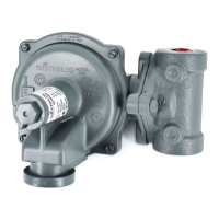
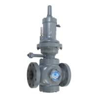
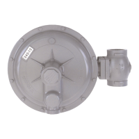
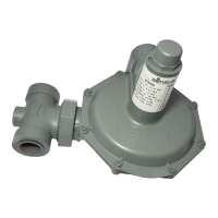
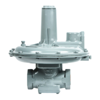
Model 461-57S Regulator
Where outlet piping increases in size near the regulator, its
generally preferable to locate the control connection in the larger size.
The 1/4" union 20 contains a small orifice, approximately
1/16" diameter. This orifice should not be removed. Also,
make certain this orifice is open and free of foreign material.
CAUTION
The diaphragm case vent must be positioned to protect against
flooding, drain water, ice formation, traffic, tampering, etc. The vent
must be protected against nest building animals, bees, insects, etc., to
prevent vent blockage and minimize chances for foreign material from
collecting in the vent side of the regulator diaphragm.
4 Check all connections for leaks.
5 Put the regulator into operation as follows: (See Figure 1)
1. Slowly open the downstream control line valve A.
2. Slowly open the downstream block valve B.
3. Very slowly open the upstream block valve C.
4. Set the adjusting screw 2 for the required outlet pressure.
Turn it clockwise to increase the pressure and
counterclockwise to decrease it. Only make this
adjustment when gas is actually flowing through the regulator.
CAUTION
Turn gas on very slowly. If an outlet stop valve is used, it
should be opened first. Do not overload diaphragm with a
sudden surge of inlet pressure. Monitor the outlet pressure
during start-up to prevent an outlet pressure overload.
5. After adjustment is complete, the locknut 3 should be
tightened firmly and the seal cap 1 replaced.
6 To shut down, carefully close valves C, B, and A in that order.
Introduction
The heart of the Model 461-57S is the “Roll-Out” Diaphragm. The
461-57S is a spring regulator with performance which approxi-
mates that of a pilot operated regulator. The “Roll-Out” Diaphragm
makes this exceptional performance possible because its unique
action reduces “droop” to a minimum (“droop” being fall off in
outlet pressure as a spring regulator opens to increase flow).
Installation and Start-Up
1 Thoroughly purge inlet piping to remove dirt and debris which
could damage the regulator or impair its operation. If this
cannot be done, a filter or strainer should be installed ahead
of the regulator (see Sensus Bulletin RDS-1498, Regulator
Pressure Ratings). Make certain that regulator is free of any
dirt or foreign matter that might have collected.
2 Place regulator in the line with high pressure connected to the
inlet side (be sure that shipping screens or covers, if used, are
removed from the inlet and outlet).
On flanges, tighten bolts evenly.
Where required, the regulator may be inverted. It may also be
installed in a vertical line. However, if installed in a vertical
line, there could be excessive wear in anti-friction bushing.
3 From the 1/4" union 20 extend pipe or tubing to the control
connection into the oulet piping. (See Figure 1 on page 2.)
This control piping should not be less than 1/4" in size and
should be adequately protected against breakage (regulators
go wide open if the control line is broken.)
CAUTION
It is the user's responsibility to assure that all regulator vents and/or
vent lines exhaust to a non-hazardous location away from ANY
POTENTIAL sources of ignition. Where vent lines are used, it is the
user's responsibility to assure that each regulator is individually vented
and that common vent lines ARE NOT used.
The regulator will work to deliver the pressure, for which it is
adjusted, at that point in the outlet piping where the control
connection is located.
In general the control connection should be at least eight pipe
diameters from the regulator and should be in as straight a
run of pipe as possible.
The control connection should be clean and smooth, free of
rough edges, welding “icicles”, etc.
Outlet Pressure Color of Nominal
Range Spring Diaphragm Size (I.D.)
3 to 6 psi Yellow
5 to 9 psi Gray
7-1/2 to 15 psi Blue
12-1/2 to 30 psi Red 5" all ranges
25 to 55 psi Brown
50 to 75 psi Black
70 to 100 psi Brown plus White*
*White colored spring is nested within brown.
Maximum Inlet Pressures for all Regulator Body Types
Maximum Working Maximum
Pressure Inlet
Regulator Body Type 461 Body Materials of Body Pressure
Screwed End Cast Iron (ASTM A126-71 Class B) 250 psi 250 psi
Flanged ANSI 125 lb. FF Cast Iron (ASTM A126-71 Class B) 175 psi 175 psi
Flanged ANSI 250 lb. RF Ductile Iron (ASTM A395-71 gr 60-4-18) 575 psi 575 psi
Flanged ANSI 300 lb. RF Cast Steel (ASTM A216-70a gr WCB) 720 psi 720 psi
Flanged ANSI 600 lb. RF Cast Steel (ASTM A216-70a gr WCB) 1200 psi 1000 psi
Spring Ranges
 Loading...