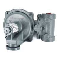
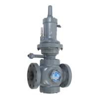
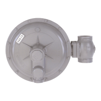
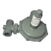
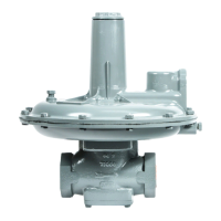
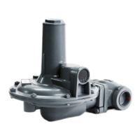
The Sensus Models 461-S, 461-8S, and 461-12S Regulators are general-purpose gas pressure regulators designed for intermediate and larger loads. They are suitable for use with natural gas, air, dry CO2, propane, butane, and other gases.
Function Description
These regulators control gas pressure by maintaining a desired outlet pressure. They can be configured as either double seat balanced valve assemblies or single seat balanced valve assemblies. The regulator works by sensing the downstream pressure through a control line and adjusting the valve position to maintain the set pressure. The vent connection is crucial for safety, providing an escape path for flammable gas, and must be located in a safe, non-hazardous area.
Important Technical Specifications
-
Maximum Inlet Pressures:
- 2" Screwed only (Cast Iron body): 250 psi
- Flanged ANSI 125 (Cast Iron body): 175 psi*
- Flanged ANSI 250 (Ductile Iron body): 575 psi*
- Flanged ANSI 300 (Cast Steel body): 720 psi*
- Note: Exceptions based on diaphragm size:
- 12" diaphragm (Cast Iron): 100 psi
- 8-1/2" diaphragm (Cast Iron): 175 psi
- 12" diaphragm (Aluminum): 100 psi
- 8" diaphragm (Aluminum): 175 psi
-
Valve Material Selection (limited by inlet pressure and differential):
- Buna-N: Max Inlet Pressure Rating 575 psi, Max Pressure Differential Rating 250 psi
- Poly-U Red: Max Inlet Pressure Rating 720 psi, Max Pressure Differential Rating 400 psi
- Poly-U Tan: Max Inlet Pressure Rating 1200 psi, Max Pressure Differential Rating 600 psi
-
Temperature Limits:
- Operating temperatures from -20°F to 150°F.
-
Regulator Body Types and Face-to-Face Dimensions (F):
- Screwed: 6-1/2"
- Flanged ANSI 125 FF: 10"
- Flanged ANSI 250 FF: 10-1/2"
-
Spring Ranges (Outlet Pressure):
- Model 461-12S (Aluminum Diaphragm Case):
- 3-1/2" to 6-1/2" w.c. (Red)
- 5" to 8-1/2" w.c. (Blue)
- 6" to 14" w.c. (Green)
- 12" to 28" w.c. (Orange)
- 1 psi to 2 psi (Black)
- 1-1/2 psi to 3 psi (Cadmium)
- Model 461-S (Cast Iron Diaphragm Case):
- 3 to 6 psi (Blue)
- 5 to 10 psi (Red)
- 2 to 10" w.c. (Aluminum)
- 4 to 16" w.c. (Green)
- 7 to 29" w.c. (Yellow)
- 1.5 to 1.75 psi (Gray)
- 1 to 3.5 psi (Blue)
- Model 461-8S (Aluminum Diaphragm Case):
- 1 psi to 2 psi (Orange)
- 2 psi to 4-1/4 psi (Black)
- 3 psi to 6-1/2 psi (Cadmium)
- 6 psi to 10 psi (Cadmium outer / White inner)
-
Capacity Correction Factors for Other Gases:
- Air (specific gravity 1.0): 0.77
- Propane (specific gravity 1.53): 0.63
- 1350 BTU Propane-Air mixture (specific gravity 1.20): 0.71
- Nitrogen (specific gravity 0.97): 0.79
- Dry CO2 (specific gravity 1.52): 0.63
- Correction Factor = 0.60 / Specific gravity of the gas
Usage Features
- Installation:
- Requires thorough purging of inlet piping to remove dirt and debris. A filter or strainer should be installed if purging is not possible.
- Flow direction must be correct (high pressure to inlet side).
- Shipping screens or covers must be removed.
- Bolts on flanges must be tightened evenly; pipe dope applied to male threads only for screwed connections.
- Can be inverted if required.
- For outdoor installation, the vent should face downward to prevent water or foreign matter entry.
- Control line installation: must be sturdy, pitched to drain away from the regulator, free of moisture pockets. Minimum size: 1/4" steel tubing/pipe for 461-12S and 461-8S; 1/2" steel pipe for 461-S.
- Control connection location: at least eight pipe diameters downstream from the regulator in a straight run, on top or side of the pipe, clear of turbulence sources.
- The 461-S models' control line unions contain a 1/16" diameter orifice that must not be removed and must be clear.
- All connections must be checked for leaks.
- Start-Up Procedure:
- Turn gas on very slowly. If an outlet stop valve is used, it must be opened first.
- Monitor outlet pressure to prevent overload.
- Slowly open downstream control line valve (A), then downstream block valve (B), then upstream block valve (C).
- Ensure valves (A), (B), and (C) are fully opened after adjustment.
- Adjustment:
- Adjusting screw (3 or 3a) is used to set the required outlet pressure. Turn clockwise to increase pressure, counterclockwise to decrease.
- Adjustment should only be made when gas is flowing.
- Remove seal cap (1, 1a, or 1b) and loosen locknut (if applicable) before adjustment.
- Tighten locknut and replace seal cap after adjustment to prevent unstable operation.
- Shut-Down Procedure:
- Carefully close valves (C), (B), and (A) in that order.
- Over-Pressurization Protection:
- Protection for downstream piping and regulator low-pressure chambers is mandatory to prevent over-pressurization due to regulator malfunction or lock-up failure. This can be achieved with a relief valve, monitor regulator, or shut-off device.
- Monitoring:
- Models 461-S, 461-8S, and 461-12S are excellent for monitoring applications, acting as a standby regulator in series.
- Fast response allows quick takeover.
- Can be located upstream or downstream.
- When two identical 461 regulators are used (one as monitor), total maximum capacity is 70% of one regulator's capacity.
- Buried Service:
- These regulators are not recommended for buried service.
Maintenance Features
- General Servicing Notes:
- Regulator must be entirely depressurized before servicing.
- Quick visual inspection of the valve is possible by removing inspection plates (33). These plates also provide improved access for servicing or adjusting.
- Valve and body parts are interchangeable with other Model 461 regulators.
- Carefully note location and position of disassembled parts for correct reassembly. Inspect and replace worn or damaged parts.
- Use lubricants sparingly, avoiding tacky surfaces in the gas stream. Moly or silicone type lubricants are recommended; avoid petroleum-based types.
- A small amount of silicone spray release agent can lubricate the stem O-ring for free movement and a tight seal. Silicone-based lubricant helps assure tightness of other O-rings and tetraseals.
- Periodic Inspection:
- Regulators are pressure control devices with numerous moving parts subject to wear. A periodic inspection schedule, with frequency determined by service severity and applicable laws, is necessary to assure continuous satisfactory operation.
- Servicing Double Seat Balanced Valve Assembly:
- Remove seal cap (1, 1a, or 1b) and mark adjustment position (3 or 3a).
- Remove bottom inspection plate (14) and unscrew valve assembly from diaphragm assembly.
- Unscrew orifice (18) with a socket wrench (1-1/2" hex deep socket).
- If valve assembly doesn't need changes, replace without disturbing set screw (12g), backing off 1/2 to 1 full turn after bottoming.
- For new parts, disassemble valve assembly by loosening set screw (12g), unscrewing 12h from 12b, and then unscrewing nut (12e) and part (12j).
- Reassemble upper and lower half valve assemblies.
- Insert upper half valve assembly (12b onto 11h), then orifice (18), then lower half valve assembly (12h onto 12b).
- Perform valve lock-up adjustment: Seat upper valve against orifice (19), screw up lower half valve assembly (12h onto 12b) until seated against (18), then firmly tighten set screw (12g).
- Screw entire valve assembly up (12b onto 11h) until it bottoms, then back off 1/2 to 1 full turn.
- Replace bottom inspection plate (14), engaging pin (13) with slot in 12j, rotate 14 until holes line up, and install cap screws (16).
- Replace removed parts and return adjustment to original setting.
- Servicing Single Seat Balanced Valve Assembly:
- Remove seal cap (1, 1a, or 1b) and mark adjustment position (3 or 3a).
- Remove bottom inspection plate (14).
- Remove locknut (12e), then slip off valve (12d) and retainer (12c).
- Orifice (18) can be removed with a socket wrench (1-1/2" hex deep socket). Reassemble in reverse order.
- If stem (12b) or valve guide (30) need removal, first remove lower diaphragm case (24).
- Note: single seat balanced valve does not require lock-up adjustment.
- Note: orifice (18) must be the same size as stem guide (30).
- Replace bottom inspection plate (14).
- Replace removed parts and return adjustment to original setting.
- Changing Spring:
- Remove seal cap (1, 1a, or 1b) and adjustment parts (3, 3a, 5, 7a, 7b, 8, 9).
- Insert the new spring, ensuring it nests correctly onto part (11b).
- Replace remaining parts.
- Servicing Diaphragm:
- Remove seal cap (1, 1a, or 1b) and mark adjustment position (3 or 3a).
- Remove bolts (22) and carefully remove upper diaphragm case (21).
- Turn diaphragm assembly counterclockwise (unscrewing 11h from 12b) and remove.
- To disassemble diaphragm assembly, remove nut (11a). Note abrasive side of emery cloth washers against diaphragm during reassembly.
- Screw diaphragm assembly back into place (11h into 12b) until it bottoms, then back off 1/2 to 1 full turn.
- Carefully reinstall upper diaphragm case (21), ensuring diaphragm is not pinched between upper and lower cases (21 and 24).
- Make sure travel indicator (45) is working. Tighten bolts (23-22) evenly.
- Insert spring (9), ensuring it nests correctly onto part (11b).
- Replace remaining parts and return adjustment to original setting.