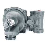
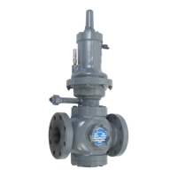
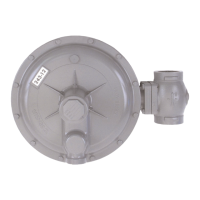
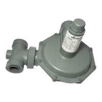
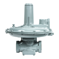
The Sensus Model 461-57S Regulator is a spring-operated device designed for pressure control, primarily in natural gas applications, but also suitable for LP gas, nitrogen, dry CO2, and air. Its core component is the "Roll-Out" Diaphragm, which contributes to its exceptional performance, allowing it to approximate the characteristics of a pilot-operated regulator. This unique diaphragm action minimizes "droop," which is the fall-off in outlet pressure as the regulator opens to increase flow.
Function Description:
The regulator's primary function is to maintain a desired outlet pressure by adjusting the flow of gas. It achieves this through the interaction of the "Roll-Out" Diaphragm, springs, and valve assembly. When the outlet pressure drops, the diaphragm moves, causing the valve to open further and increase flow until the set pressure is restored. Conversely, if the outlet pressure rises, the valve closes to reduce flow. The control connection, typically located at least eight pipe diameters downstream from the regulator in a straight run of pipe, senses the outlet pressure and feeds it back to the diaphragm for adjustment. A small orifice (approximately 1/16" diameter) within the 1/4" union of the control piping is crucial for proper operation and must remain clear of foreign material.
Important Technical Specifications:
- Body Materials:
- Cast Iron (ASTM A126-71 Class B): Screwed End, Flanged ANSI 125 lb. FF
- Ductile Iron (ASTM A395-71 gr 60-4-18): Flanged ANSI 250 lb. RF
- Cast Steel (ASTM A216-70a gr WCB): Flanged ANSI 300 lb. RF, Flanged ANSI 600 lb. RF
- Maximum Working Pressure of Body:
- Cast Iron: 250 psi (Screwed End), 175 psi (Flanged ANSI 125 lb. FF)
- Ductile Iron: 575 psi (Flanged ANSI 250 lb. RF)
- Cast Steel: 720 psi (Flanged ANSI 300 lb. RF), 1200 psi (Flanged ANSI 600 lb. RF)
- Maximum Inlet Pressure:
- Cast Iron: 250 psi (Screwed End), 175 psi (Flanged ANSI 125 lb. FF)
- Ductile Iron: 575 psi (Flanged ANSI 250 lb. RF)
- Cast Steel: 720 psi (Flanged ANSI 300 lb. RF), 1000 psi (Flanged ANSI 600 lb. RF)
- Maximum Emergency Pressures (without damage):
- Inlet: 275 psi (Screwed End), 200 psi (ANSI 125 lb), 630 psi (ANSI 250 lb), 800 psi (ANSI 300 lb), 1100 psi (ANSI 600 lb)
- Outlet: Set-point + 25 psi
- Diaphragm Case: 175 psi
- Outlet Pressure Ranges (Springs):
- Yellow: 3 to 6 psi
- Gray: 5 to 9 psi
- Blue: 7-1/2 to 15 psi
- Red: 12-1/2 to 30 psi
- Brown: 25 to 55 psi
- Black: 50 to 75 psi
- Brown plus White*: 70 to 100 psi (*White colored spring is nested within brown)
- Nominal Diaphragm Size (I.D.): 5" for all ranges
- Face to Face Dimensions:
- Screwed: 6-1/2 in.
- Flanged ANSI 125: 10 in.
- Flanged ANSI 250: 10-1/2 in.
- Flanged ANSI 300: 10-1/2 in.
- Flanged ANSI 600: 11-1/4 in.
- Temperature Limits: -20°F to 150°F
- Correction Factors for Other Gases: Air (0.77), Propane (0.63), 1350 BTU Propane-Air Mix (0.71), Nitrogen (0.79), Dry Carbon Dioxide (0.63). For other noncorrosive gases, the correction factor is 0.6 / Specific Gravity of the Gas.
Usage Features:
- Installation:
- Inlet piping must be thoroughly purged to remove dirt and debris. A filter or strainer is recommended if purging is not possible.
- The regulator can be installed inverted or in a vertical line, though vertical installation may lead to excessive wear in the anti-friction bushing.
- The diaphragm case vent must be positioned to protect against flooding, ice, traffic, tampering, and animal nesting to prevent blockage and foreign material accumulation.
- Control piping (1/4" minimum size) must extend from the 1/4" union to the outlet piping, adequately protected against breakage.
- The control connection should be clean, smooth, and free of obstructions.
- Start-Up Procedure:
- Slowly open the downstream control line valve (A).
- Slowly open the downstream block valve (B).
- Very slowly open the upstream block valve (C).
- Adjust the adjusting screw for the required outlet pressure (clockwise to increase, counterclockwise to decrease), only when gas is flowing.
- Firmly tighten the locknut and replace the seal cap after adjustment.
- Caution: Turn gas on very slowly to avoid overloading the diaphragm with a sudden surge of inlet pressure. Monitor outlet pressure during start-up.
- Shut-Down Procedure: Carefully close valves C, B, and A in that order.
- Overpressurization Protection: Downstream piping and low-pressure chambers must be protected against overpressurization due to regulator malfunction or lockup failure. This can be achieved using a relief valve, monitor regulator, shutoff device, or similar mechanisms, adhering to federal codes, state codes, and Sensus Bulletin RDS-1498.
- Buried Service: Not recommended.
Maintenance Features:
- General Servicing:
- Ensure the regulator is completely depressurized before servicing.
- Quick visual inspection of the valve is possible by removing inspection plates 33. These plates also provide improved access for servicing and adjustment.
- Diaphragm 11d, springs 9, and other diaphragm-related parts (except 11h stud) are interchangeable with Model 441-57S Regulators. Valve and body parts are interchangeable with other 461 Regulators (461-S, 461-X57, 1100, 1200, 461-2100).
- Lubricants (moly or silicone type, avoid petroleum-based) should be used sparingly on tacky surfaces to prevent dirt accumulation. Lubricate stem 12b, guide 12j, and stem O-rings 12a & 12n with dry silicon lubricant for free movement and a tight seal. Lubricating other O-rings and tetraseals helps assure tightness.
- Double Seat Balanced Valve Assembly Service:
- Remove seal cap 1, back off adjusting screw 2, remove housing cover 6, and spring 9.
- Remove bottom inspection plate 14, and unscrew valve assembly from diaphragm assembly.
- Unscrew orifice 18 with a 1-1/2" hex deep socket. Remove orifice and valve assembly through bottom opening.
- If valve assembly and orifice are in good condition, screw orifice 18 firmly into place (without disturbing set screw 12g). Screw top end of 12b into 11h until it bottoms, then back off 1/2 to 1 full turn.
- For new parts, disassemble valve assembly by loosening set screw 12g, unscrewing 12h from 12b, and unscrewing nut 12e and part 12j.
- Reassemble upper half valve assembly (12a, 12b, 12c, 12d, 12e) and lower half (12f, 12g, 12h, 12c, 12d, 12j).
- Insert through bottom opening: upper half valve assembly (screw 12b onto 11h until it bottoms, then back off 1/2 to 1 full turn), orifice 18 (screw firmly into place), lower half valve assembly (screw onto upper half by 3 or 4 turns).
- Make valve lock-up adjustment: Seat upper valve against orifice 19 while screwing up lower half valve assembly (12h screws onto 12b until lower valve is seated against 18). Then, firmly tighten set screw 12g.
- Screw entire valve assembly up (top of 12b screws onto lower end of 11h until it bottoms), then back off 1/2 to 1 full turn (important).
- Complete assembly as per steps 6-10 under "To Assemble 461-57S".
- Single Seat Balanced Valve Assembly Service:
- Remove seal cap 1, back off adjusting screw 2, remove housing cover 6, and spring 9.
- Remove bottom inspection plate 14.
- Remove locknut 12e, then slip off valve 12d and retainer 12c. Orifice 18 can be removed with a 1-1/2" hex deep socket. Reassemble in reverse order.
- If removing stem 12b or valve guide 30, first remove lower diaphragm case 21. Use a 1-1/2" hex deep socket for 30.
- Note: Single seat balanced valve does not require lock-up adjustment.
- Note: Orifice 18 must be the same size as stem guide 30 (e.g., 1" 18 with 1" 30).
- Reassemble as per applicable steps under "To Assemble 461-57S".
- Spring Change:
- Remove seal cap 1, back off adjusting screw 2, remove housing cover 6, and spring 9.
- Insert the new spring, ensuring it nests correctly into part 11c and that the travel indicator bracket 36k is in place. Visually inspect the diaphragm for uniform roll-out.
- Complete as per steps 8, 9, and 10 under "To Assemble 461-57S".
- Diaphragm Service:
- Remove seal cap 1, back off adjusting screw 2, remove housing cover 6, and spring 9.
- Remove bolts 23 and carefully remove upper diaphragm case 10.
- Turn diaphragm assembly counterclockwise until 11h unscrews from 12b, then remove assembly and inspect diaphragm.
- If a new diaphragm 11d is needed, remove nut 11a and disassemble.
- When reassembling, ensure the fabric side and gasket of the diaphragm are toward the vent side, and the rubber side toward the pressure side. The gasket is always on the spring side.
- To minimize rolling friction and sticking, coat the fabric side of the diaphragm with Molycote or equivalent graphite-based lubricant before installation. Screw diaphragm assembly back into place (11h screws into 12b until it bottoms), then back off 1/2 to 1 full turn (important).
- Form the roll into roll-out diaphragm 11d, then carefully reinstall upper diaphragm case 10. Ensure the diaphragm is not pinched and the roll-out loop is uniformly full and even. Tighten bolts 23 and nuts 22 evenly.
- Replace spring, etc., per steps 7-10 under "To Assemble 461-57S".
- Disassembly (To Take 461-57S Apart):
- Remove seal cap 1, loosen nut 3, back off adjusting screw 2, remove cover cap screws 16, housing cover 6, gasket 28, and spring 9.
- Remove bolts 23 and nuts 22 and upper diaphragm case 10.
- Unscrew diaphragm assembly 11 from stem 12b.
- Remove lower case to body cap screws 16 and lower diaphragm case 21.
- Remove valve assembly and orifice 18 as per previous sections.
- Remove inlet orifice 19 (or guide 30) through top opening using a 1-1/2" socket wrench.
- Assembly (To Assemble 461-57S):
- Install valve parts through top opening (guide 30 with stem 12b plus pin 12m or orifice 19).
- Install lower diaphragm case 21.
- Install valve assembly and orifice 18 as per previous instructions, making lock-up adjustment on double seat valve.
- Screw diaphragm assembly back into place (11h screws into 12b until it bottoms, then back off 1/2 to 1 full turn – important).
- Install upper diaphragm case as per step 7 under "To Service Diaphragm".
- Replace bottom inspection plate 14 (with double seat valve, engage pin in 13 with slot in lower end of 12j, then rotate 14 until holes line up to install cap screws 16).
- Insert the spring, ensuring it nests correctly into part 11c and that the travel indicator bracket is in place. Visually inspect the diaphragm for uniform roll-out.
- Insert top spring button 7a and ball bearing 7b, ensuring it is nested correctly on the spring.
- Install housing cover gasket 28 and housing cover 6. Ensure the lower end of adjusting screw 2 goes into the hole in button 7a. Install housing cover screws 16.
- Set adjusting screw 2 for desired outlet pressure, firmly tighten nut 3 and replace seal 4 and cap 1.
- Periodic Inspection: Regulators are pressure control devices with numerous moving parts subject to wear. A periodic inspection schedule, with frequency determined by service severity and regulations, is essential for continuous satisfactory operation.