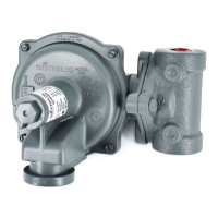
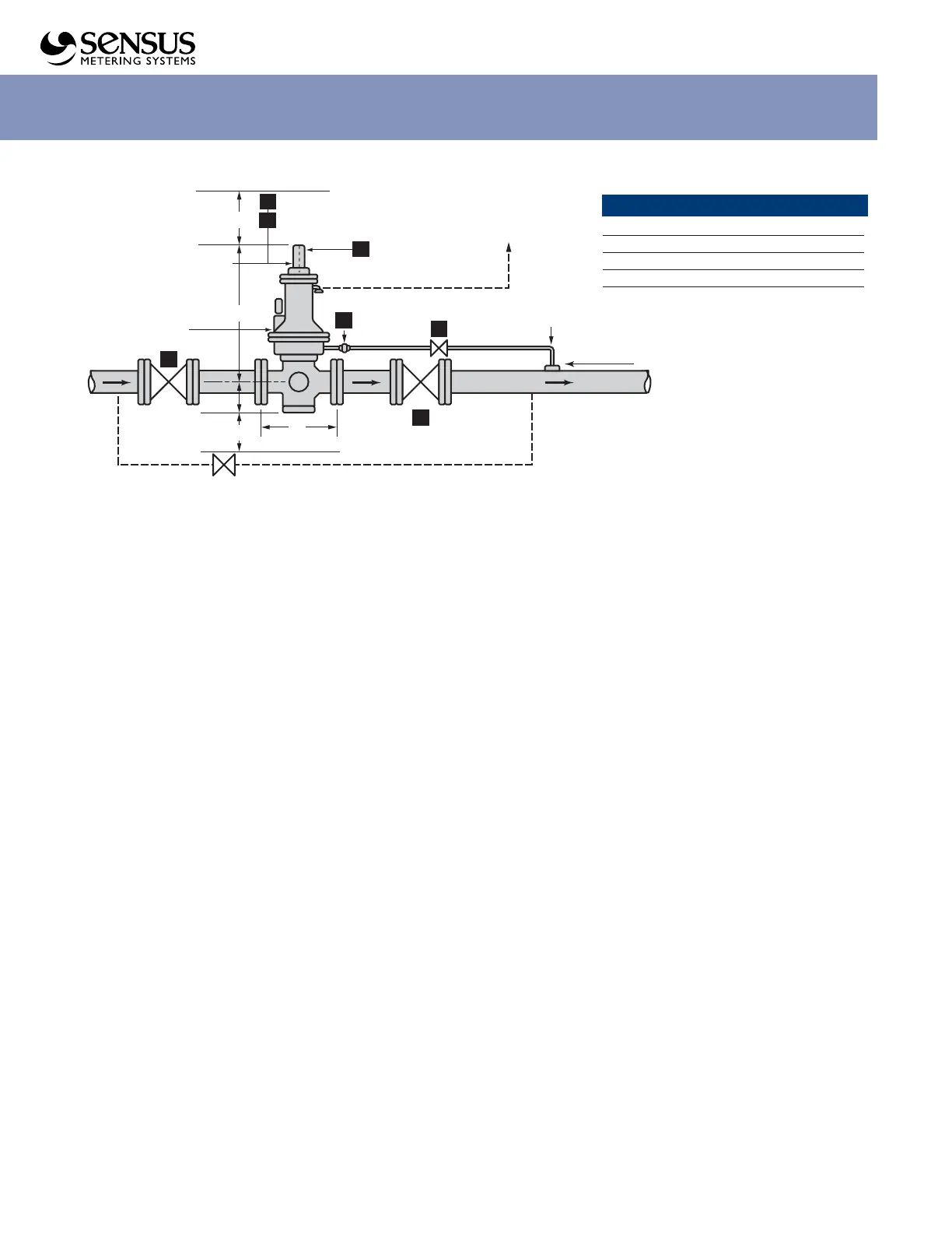
5"
(Minumum Service Space)
Self Adjustment
Screw for Desired
Outlet Pressure
2
3
1
Vent
Remove Vent
(If Required)
461-57S
20.5"
20
A
Downstream
Control Line
Control Line
Connection
B
Outlet
8"
4"
F
Minumum
Service Space
(Bypass (If Required)
Inlet
C
3
Installation and Maintenance Instructions
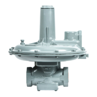
Model 461-57S Regulator
Servicing and Adjustment
General Notes (see Illustration on page7)
1 Make sure the regulator is entirely depressured before servicing.
2 A quick visual inspection of the valve can be made by
removing inspection plates 33 from the sides of the body.
These also provide greatly improved access to the valve when
servicing or adjusting.
3 The diaphragm 11d, the springs 9, and all other parts from
the diaphragm up (except the 11h stud) are interchangeable
with the Model 441-57S Regulator. Valve and body parts are
interchangeable with other 461 Regulators
(461-S, 461-X57, 1100, 1200, 461-2100).
4 Use lubricants sparingly and with care to avoid exposing tacky
surfaces to the gas stream. Such surfaces could cause dirt
accumulation on close clearance parts.
Use moly or silicone type lubricants. Avoid the use of
petroleum base types.
Lubricate the stem 12b, guide 12j and stem O-rings 12a
& 12n with dry silicon lubricant to help assure free
movement and a tight seal.
An application of lubricant to other O-rings and the tetraseals
in the regulator will also help assure their tightness.
5 When using double seat balanced valve assembly, bushing 13
must be screwed firmly into place. When using single seat
balanced valve assembly, bushing 13 must be removed.
To Service Double Seat Balanced Valve Assembly
1 Remove seal cap 1, back off adjusting screw 2, remove
housing cover 6, and remove spring 9.
2 Remove bottom inspection plate 14, and unscrew valve
assembly intact from diaphragm assembly (12b unscrews
from 11h).
3 Unscrew orifice 18 with socket wrench (1-1/2" hex, deep
socket). Remove orifice 18 and valve assembly intact
through bottom opening.
4 If valve assembly and orifice are alright, screw orifice 18
firmly into place. Replace without disturbing set screw 12g.
Top end of 12b screws into 11h until it bottoms and should
then be backed off 1/2 to 1 full turn.
5 If new parts are needed, disassemble valve assembly by
loosening set screw 12g and unscrewing 12h from 12b, and
then unscrewing nut 12e and part 12j.
6
Replace parts as required, then reassemble upper half valve
assembly (parts 12a, 12b, 12c, 12d, 12e) and lower half
(parts 12f, 12g, 12h, 12c, 12d, 12j).
7 Insert through bottom opening:
a. upper half valve assembly - screw 12b onto 11h until
it bottoms then back off 1/2 to 1 full turn.
b. orifice 18 - screw firmly into place.
c. lower half valve assembly - screw onto upper half
by 3 or 4 turns (12h screws onto 12b).
8 Make the valve lock-up adjustment. Seat the upper valve
against orifice 19 while screwing up the lower half valve
assembly (12h screws onto 12b until the lower valve is
seated against 18). Then, firmly tighten set screw 12g.
a. To seat the upper valve against orifice 19, either reach
it through the body side opening or remove diaphragm
assembly and pull top end of stem 12b upwards.
b. Tighten 12g with screwdriver through body side
opening. If necessary, turn the entire valve assembly
(carefully – do not disturb adjustment to face 12g
toward side opening).
c. 12g must tighten against flat area at top of 12h to
correctly lock the adjustment.
9 Screw entire valve assembly up (top of 12b screws onto
lower end of 11h until it bottoms), then back off 1/2 to 1
full turn - this is important.
10 Complete assembly as per steps 6 thru 10 under
“To Assemble 461-57S”.
Figure 1. Typical Arrangement and Dimensions (indoor and outdoor installation)
Regulator Body Type (Face to Face, in.)
Screwed6-1/2
Flanged ANSI 125 10
Flanged ANSI 250 10-1/2
Flanged ANSI 300 10-1/2
Flanged ANSI 600 11-1/4
 Loading...