4
Installation and Maintenance Instructions
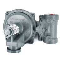
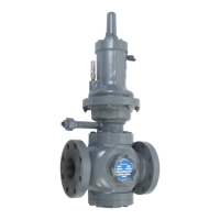
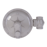
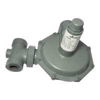
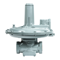
Model 461-57S Regulator
To Service Single Seat Balanced Valve Assembly
1 Remove seal cap 1, back off adjusting screw 2, remove
housing cover 6, and remove spring 9.
2 Remove bottom inspection plate 14.
3 Remove locknut 12e, then slip off valve 12d and retainer 12c.
Orifice 18 can be removed with socket wrench
(1-1/2" hex, deep socket). Reassemble in reverse order.
4 If it should be necessary to remove stem 12b or valve guide
30, do so by first removing lower diaphragm case 21
(steps 2 thru 4 under “To Take 461-57S Apart”). Use socket
wrench (1-1/2" hex, deep socket) for 30.
5 Note – single seat balanced valve does not require any
lock-up adjustment.
6 Note – orifice 18 must be same size as stem guide 30.
(1" 18 with 1" 30, and 11/16" 18 with 11/16" 30). Do not use
11/16" size of one with 1" size of the other.
7 Reassemble as per applicable steps under “To Assemble 461-57S”.
To Change Spring
1 Remove seal cap 1, back off adjusting screw 2, remove
housing cover 6, and remove spring 9.
2 Insert the new spring. Be sure it nests correctly into part 11c and
that travel indicator bracket 36k is in place. Also, make a visual
inspection of the diaphragm before inserting the spring to be sure
the roll-out is uniform and in place. (Use a flashlight, if necessary).
3 Complete as per steps 8, 9, and 10 under “To Assemble 461-57S”.
To Service Diaphragm
1 Remove seal cap 1, back off adjusting screw 2, remove
housing cover 6, and remove spring 9.
2 Remove bolts 23 and then carefully remove upper diaphragm case 10.
3 Turn diaphragm assembly counterclockwise until
11h unscrews
from 12b, then remove assembly and inspect diaphragm.
4 If a new diaphragm 11d is required, remove nut 11a
and disassemble.
5 When reassembling, be sure that fabric side and gasket of
diaphragm is toward the vent side of the regulator and the
rubber side of diaphragm toward the pressure side. The
gasket is always placed on the spring side of diaphragm.
6 To minimize rolling friction and prevent sticking, coat the
fabric side of the diaphragm with Molycote, or equivalent
graphite based lubricant, before installation Screw diaphragm
assembly back into place. (11h screws into 12b until it
bottoms), then back off 1/2 to 1 full turn - this is important.
7 Form roll into roll-out diaphragm 11d, then carefully reinstall
upper diaphragm case 10. Diaphragm must not be pinched
between upper and lower cases, 10 and 21. Also,
roll-out loop must be uniformly full and even. It should be in
place as shown of the cross-section drawing. Tighten
bolts 23 and nuts 22 evenly.
8 Replace spring, etc., per steps 7 thru 10 under
“To Assemble 461-57S” below.
To Take 461-57S Apart
1 Remove seal cap 1, loosen nut 3, back off adjusting screw 2,
remove cover cap screws 16, remove housing cover 6,
remove gasket 28, and remove spring 9.
2 Remove bolts 23 and nuts 22 and upper diaphragm case 10.
3 Unscrew diaphragm assembly 11 from stem 12b.
4 Remove lower case to body cap screws 16 and remove lower
diaphragm case 21.
5 Remove valve assembly and orifice 18 per previous sections
on servicing valve assembly.
6 Remove inlet orifice 19 (or guide 30) through top opening
using 1-1/2" socket wrench.
To Assemble 461-57S
1 Install valve parts as required through top opening
(guide 30
with stem 12b plus pin 12m or orifice 19).
2 Install lower diaphragm case 21.
3 Install valve assembly and orifice 18 per previous instructions
on servicing valve assemblies. Make lock-up adjustment on
double seat valve.
4 Screw diaphragm assembly back into place. 11h screws into
12b until it bottoms, then back off 1/2 to 1 full turn
- this is important.
5 Install upper diaphragm case per step 7 under
“To Service Diaphragm”.
6 Replace bottom inspection plate 14 (with double seat valve,
engage pin in 13 with slot in lower end of 12j,
then rotate 14 until holes line up to install cap screws 16).
7 Insert the spring. Be sure it nests correctly into part 11c and
that travel indicator bracket is in place. Also, make a visual
inspection of the diaphragm before inserting the spring to be
sure the roll-out is uniform and in place.
(Use a flashlight, if necessary).
8 Inset top spring button 7a and ball bearing 7b. Be sure it is
nested correctly on the spring.
9 Install housing cover gasket 28 and housing cover 6. Be sure
the lower end of adjusting screw 2 goes into the hole in
button 7a. Install housing cover screws 16.
10 Set adjusting screw 2 for desired outlet pressure, firmly
tighten nut 3 and replace seal 4 and cap 1.
CAUTION
Regulators are pressure control devices with numerous moving
parts subject to wear that is dependent upon particular
operating conditions. To assure continuous satisfactory
operation, a periodic inspection schedule must be adhered to
with the frequency of inspection determined by the severity of
service and applicable laws and regulations.
 Loading...