12-24 VDC
R
GB
Electronic Switch
(MOSFET)
OMNI
Register
+
Signal to
12-24 VAC Relay
Signal Connections 10
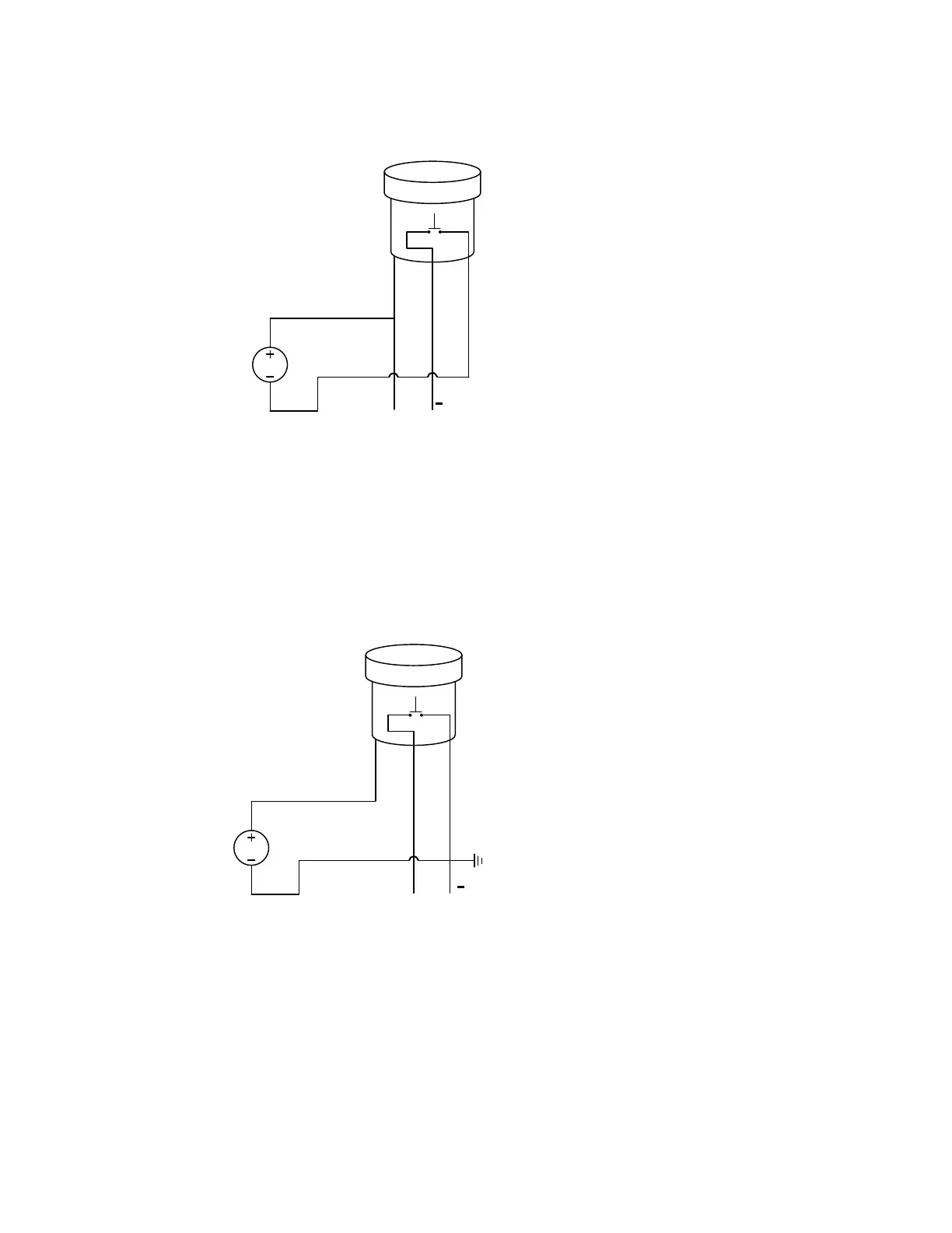
Illustration 1
Illustration 1 is used when the OMNI is connected to a PLC (e.g., in a SCADA system).
The PLC should not have an internal pull-up resistor in its input circuit (no DC voltage
at the instrument inputs). Usually the instrument must be isolated by having an optical
isolator at its inputs.
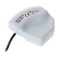
Illustration 2
Illustration 2 is used for all instruments with internal pull-up resistors. The voltage
supplied by the instrument’s input when not connected to any circuitry should not
exceed 24 Vdc nom. and must not exceed 30 Vdc max. Otherwise, it will overload the
MOSFET inside the OMNI register. The voltage supplied to the register is allowed to
be different from the instrument’s supply voltage.
Ground is common for both the OMNI register and instrument.
24 VDC
R
GB
Electronic Switch
(MOSFET)
OMNI
Register
+
Signal to Instrument,
Supplied from Instrument/
4 - 24 VDC
Ground to Instrument
(if required)