www.sentera.eu
MIW-STL-EN-002 - 30 / 07 / 2018 6 - 8
back to the table of contents
3. Fix the unit to the wall or panel using the provided screws and dowels. Mind the
correct mounting position and unit mounting dimensions (seeFig. 1 and Fig. 2).
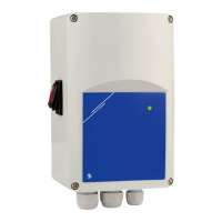
Fig. 1 Mounting dimensions Fig. 2 Mounting position
E
D
F
A
B
C
Article code A B C D E F
STL-0-15-AT
STL-0-30-AT
162 mm 96 mm 75 mm 71 mm 108,8 mm Ø 4,2
STL-0-50-AT 162 mm 96 mm 93 mm 71 mm 108,8 mm Ø 4,2
STL-0-60-AT
STL-0100-AT
205 mm 124 mm 97 mm 102 mm 140 mm Ø 4,6
Correct Incorrect
4. Insert the cables through the cable glands and do the wiring according to the
wiring diagram (see Fig. 3) using the information from section “Wiring and
connections”.
4.1 Connect the motor/fan.
4.2 Connect L1 if you want to use a lamp, valve, damper, etc. (for 3-wire
connection). L1 is powered while the regulated output is active and
connecting an item to it is optional.
4.3 Connect the power supply and earth terminals.
Fig. 3 Wiring and connections
Power supply
230 VAC ±10 % / 50 Hz
Unregulated output
230 VAC / max. 2 A
L
N
N
L1
Single-phase motor connection
ATTENTION
Make sure that you use cables with an appropriate diameter.
ATTENTION
Make sure that the connections are correct before you power the unit.
5. Set the potentiometer at Min. speed position and switch on the controller.
STL
ELECTRONIC FAN SPEED
CONTROLLER, 230 VAC

 Loading...