www.sentera.eu
MIW-STL-EN-002 - 30 / 07 / 2018 5 - 8
back to the table of contents
STANDARDS
■
Low Voltage Directive 2006/95/EC
■
EMC Directive 2004/108/EC: EN 61326
■
WEEE Directive 2012/19/EU
■
RoHs Directive 2011/65/EU
WIRING AND CONNECTIONS
L Power supply, phase 230 VAC / 50 Hz
N Power supply, neutral
L1 Unregulated output (230 VAC/max. 2 A)
PE Earth terminal
M Regulated output, phase
N Regulated output, neutral
Connections
Cable cross section: max. 2,5 mm
2
Cable gland clamping range: 5—10 mm/ 8—13 mm (STL-0100-AT)
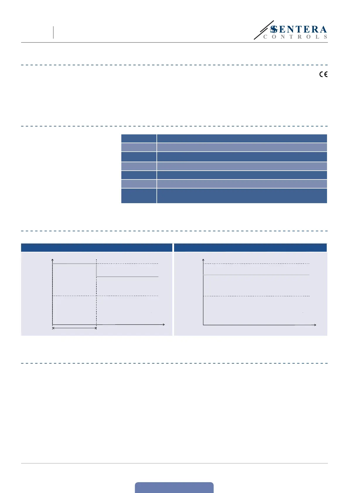
OPERATIONAL DIAGRAMS
Kick start mode Normal start mode
t [s]
230 VAC
0
External potentiometer value
Minimum
speed
t [s
230 VAC
0
External potentiometer value
Minimum
speed
MOUNTING INSTRUCTIONS IN STEPS
Before you start mounting the STL read carefully “Safety and Precautions”.
Choose a smooth surface for installation (a wall, panel and etc).
Follow these steps:
1. Make sure the STL controller is switched off and the power is disconnected.
2. Unscrew the front cover and open the enclosure. Mind the two wires that
connect the potentiometer with the printed circuit board.
STL
ELECTRONIC FAN SPEED
CONTROLLER, 230 VAC

 Loading...