8
Application range and advantages
In combination with a timer, the sera CO
2
sole-
noid valve for auto switch off 1.6 VA (Watt)
precisely regulates CO
2
switchoff during the
night or at any other time. It is suitable for
installation into present and new pH controlled
CO
2
fertilizing systems. A CO
2
pressure re -
ducing valve must be in stalled between the
sera CO
2
solenoid valve and the CO
2
gas bot-
tle .
The advantages of the sera CO
2
solenoid
valve:
• High quality precision technology – robust
and long lived
• Easy set up
• Quiet and unobtrusive
• Low electricity consumption
• Low heat dissipation ensures long life
• High pressure stability
• Suitable for all common CO
2
fertilization sys-
tems
Connection to CO
2
hoses
The solenoid valve can be connected to plas tic
hoses with 4 mm internal and 6 mm external
diameter on the intake and outlet nozzles (see
flow direction mark on the valve).
Remove the screw caps on both sides to do
so, and push them onto the hoses. Then push
the hoses firmly onto the hose nozzles. Secure
the hoses against sliding off by screw ing on the
screw caps firmly, thus fastening the hoses .
Proper hose fastening is im portant as the CO
2
gas will otherwise escape quickly. Therefore
make sure the hoses on the solenoid valve noz-
zles are not worn out.
1
2
3
Due to its low electricity consumption of 1.6 VA
(Watt), only little heat is developed. Therefore
you may, for example, simply put the solenoid
valve into the aquarium cabinet.
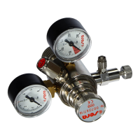
Connection to a pressure reducer ( )
Please observe the information for use of the
corresponding unit when using the sera CO
2
solenoid valve behind a pressure reducer.
When combined with the sera flore CO
2
pres-
sure reducer, the sera CO
2
solenoid valve
may only be connected to the solenoid valve by
a hose.
Please note that the screw connectors are
glued in many pressure reducers. Loosening
these connectors may affect operational safety.
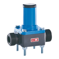
Operation
The CO
2
pressure reducer valve must be ad -
justed in a way that a maximum pressure of
2 bar is present at the sera CO
2
solenoid valve.
Now connect the sera CO
2
solenoid valve to a
timer. Set the timer clock according to the
desired CO
2
supply time. The valve will open
with a quiet clicking sound.
SAFETY PRECAUTIONS!
Please be sure to read carefully!
• The duration of CO
2
addition depends on the
lighting period, because plants can only take
up and process CO
2
under lighting.
• Do not disconnect the hose connections
while the CO
2
fertilization system is still under
pressure. First close the main and outlet
valves of the bottle and wait until no bubbles
appear in the sera flore CO
2
pressure dif-
fuser with bubble counter or the sera flore
CO
2
bubble counter any more.
4
US
Information for use
sera CO
2
solenoid valve
Please read these instructions carefully and keep for future use.
 Loading...