© Sercel 2020 - All rights reserved
〉 Possible Reason(s)
o Send / Receive connections
reversed
o Improper address and Baud Rate
o Not receiving Modbus request
(Magenta LED by Modbus
connector flashes when SPS
receives Modbus request)
No Modbus communication
18
〉 Correction
Check for proper Modbus address and Baud rate on SPS-1500 LCD
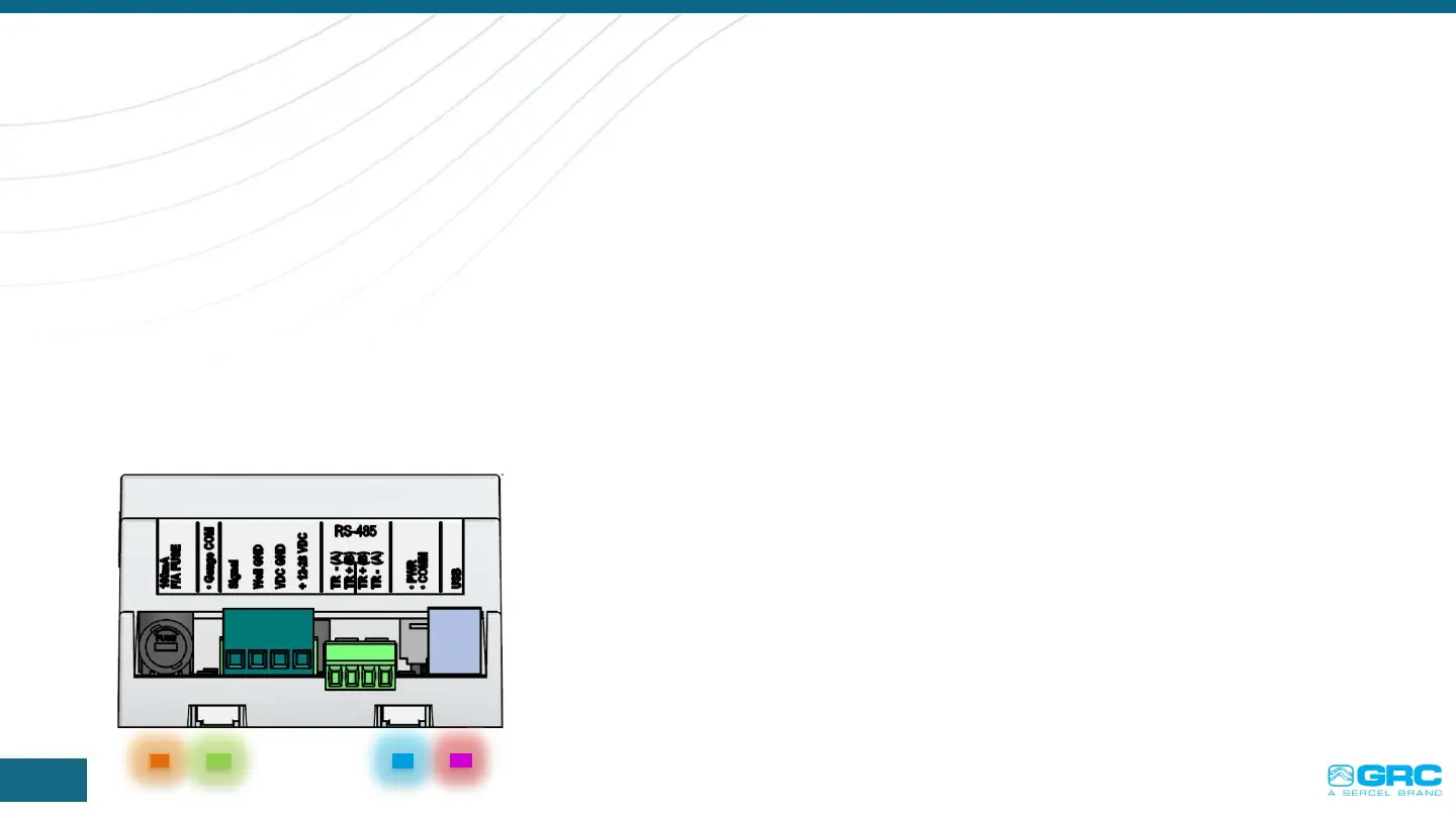
RS-485 connections
o Make sure jumpers, J6 & J7, are on SPS-1500.
o Make sure same polarity connection is going from SPS-1500 to
RS-485 adaptor board [e.g. ‘TR-’ from SPS-1500 connects to
TD(A) of RS-485 adaptor].
RS-422 connections
o Make sure jumpers, J6 & J7, are not on SPS-1500.
o Make sure all 4 wires are connected with correct polarity. For
example
o ‘TR-’ from SPS-1500 connects to TD(A) of RS-422 adaptor and –
TR+’from SPS-1500 connects to TD (B) of RS-422 adaptor.
 Loading...