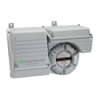
The SERVOTOUGH OxyExact 2223A Transmitter is an oxygen analyzer designed for use in safety instrumented systems (SIS). It provides stable and accurate measurements of oxygen concentration in a sample gas stream, with the primary safety function being the reliable indication of this oxygen concentration. The device is classified as a Type B subsystem, indicating it contains complex components like microprocessors and software.
Function Description:
The core function of the 2223A Oxygen Transmitter is to measure oxygen concentration. It utilizes a paramagnetic cell for this measurement. The transmitter includes comprehensive signal processing and support functions, which can optionally incorporate pressure compensation and flow alarm features, either through internally fitted options or via external inputs. The measurement data is output as a 4-20 mA current signal. Fault conditions are indicated by a solid-state relay output and by an out-of-range current from the mA output (specifically, 0 mA or 21 mA, depending on configuration). Additional status indications are provided by further solid-state relays. The transmitter is typically integrated with a 2210 or 2213 Control Unit, which facilitates additional system inputs and outputs, configuration, and display of measurements.
Important Technical Specifications:
- Safety Integrity Level (SIL): The 2223A Oxygen Transmitter is suitable for use in safety instrumented systems up to SIL 2, according to IEC 61508. This is based on hardware safety integrity.
- Hardware Fault Tolerance (HFT): The device has an HFT of 0, meaning that one fault could cause the loss of a safety function.
- Safe Failure Fraction (SFF): The SFF ranges from 91% to 92%, depending on whether internal pressure/flow compensation is enabled and the reading range (low or high).
- Average Probability of Dangerous Failure on Demand (PFDAVG):
- With Internal Press/Flow Enabled: 1.3 x 10^-3 (for both Reading Low and Reading High).
- With Internal Press/Flow Disabled: 9 x 10^-4 (Reading Low) and 8 x 10^-4 (Reading High).
These PFDAVG values are based on a Mean Time To Repair (MTTR) of 24 hours and a proof test interval (T1) of 8760 hours (approximately one year).
- Failure Rates (expressed in failures per million hours - fpmh):
- Internal Press/Flow Enabled:
- Safe failure rate (λs): 2.2 (Reading Low), 2.4 (Reading High)
- Dangerous detected failure rate (λdd): 1.4 (Reading Low), 1.2 (Reading High)
- Dangerous undetected failure rate (λdu): 0.3 (Reading Low), 0.3 (Reading High)
- Internal Press/Flow Disabled:
- Safe failure rate (λs): 1.45 (Reading Low), 1.7 (Reading High)
- Dangerous detected failure rate (λdd): 0.75 (Reading Low), 0.5 (Reading High)
- Dangerous undetected failure rate (λdu): 0.2 (Reading Low), 0.19 (Reading High)
- Output: 4-20 mA current output for oxygen concentration.
- Fault Indication: Solid-state relay output and out-of-range mA current (0 mA or 21 mA).
- Inputs: External analog inputs for pressure/cross interference compensation, and external flow sensor inputs.
Usage Features:
- Configuration: Settings for the mA output, fault relay, flow alarm, and analog inputs are configured via a 2210 or 2213 Control Unit or a 2215 Tx Interface. Access to these settings requires a password.
- mA Output Configuration: Users can set Measurement 1 and 2 to define the output range, specify a non-zero "Under Range Current," and configure "Jam" to either Low or High for fault indication. "On Service In Progress" can also be set.
- Fault Relay Configuration: The fault relay can be configured to be de-energized when inactive. Connections for the fault relay should be made to contacts that are normally open when de-energized, especially if used in SIS.
- Flow Alarm: If fitted, the internal flow alarm should be calibrated at "normal" gas flow, and alarm levels set appropriately. External flow alarm inputs can also be used.
- Analog Inputs: External measurements for pressure or cross-interference compensation can be connected and configured. This includes setting Measurement 1 and 2, Current 1 and 2 to map input current ranges to measurement ranges, and defining "Under Range Current" and "Over Range Current" for fault conditions. "Name," "Filter Factor," and "Units" can also be set.
- Password Protection: After configuration, default passwords should be changed to prevent unauthorized alterations to settings, ensuring the integrity of the safety function.
Maintenance Features:
- Proof Testing: Safety checks, including proof tests, must be carried out after installation and at regular intervals as per IEC 61508. The recommended maximum proof test interval is one year.
- Fault Resolution: Any transmitter fault conditions must be resolved before proceeding with safety checks. It is also recommended to address any "maintenance required" conditions.
- Checks (without pressure compensation):
- Ensure spurious outputs do not compromise safety.
- Verify mA output accuracy at 0.0 mA and 20.0 mA using the built-in test feature.
- Perform a full low and high calibration.
- Conduct a reference measurement with known oxygen concentration and verify mA output tolerance.
- If an internal flow sensor is present, test flow alarms by altering gas flow.
- Restore normal operation.
- Checks (with pressure compensation):
- Ensure spurious outputs do not compromise safety.
- Verify mA output accuracy at 0.0 mA and 20.0 mA.
- Check "Calibrated Pressure" in Transmitter Diagnostics against actual pressure.
- Calibrate the pressure sensor.
- Perform a full low and high calibration of the oxygen measurement.
- Calibrate pressure compensation.
- Conduct a reference measurement with known oxygen concentration and verify mA output tolerance.
- If an internal flow sensor is present, test flow alarms.
- Restore normal operation.
- Routine Calibration: Regular full calibrations are recommended as detailed in the operator manual.