2
4.0 ELECTRICAL INSTALLATION
External access to the Model 278 electrical terminations is provided on
the terminal strip at the bottom of the unit.
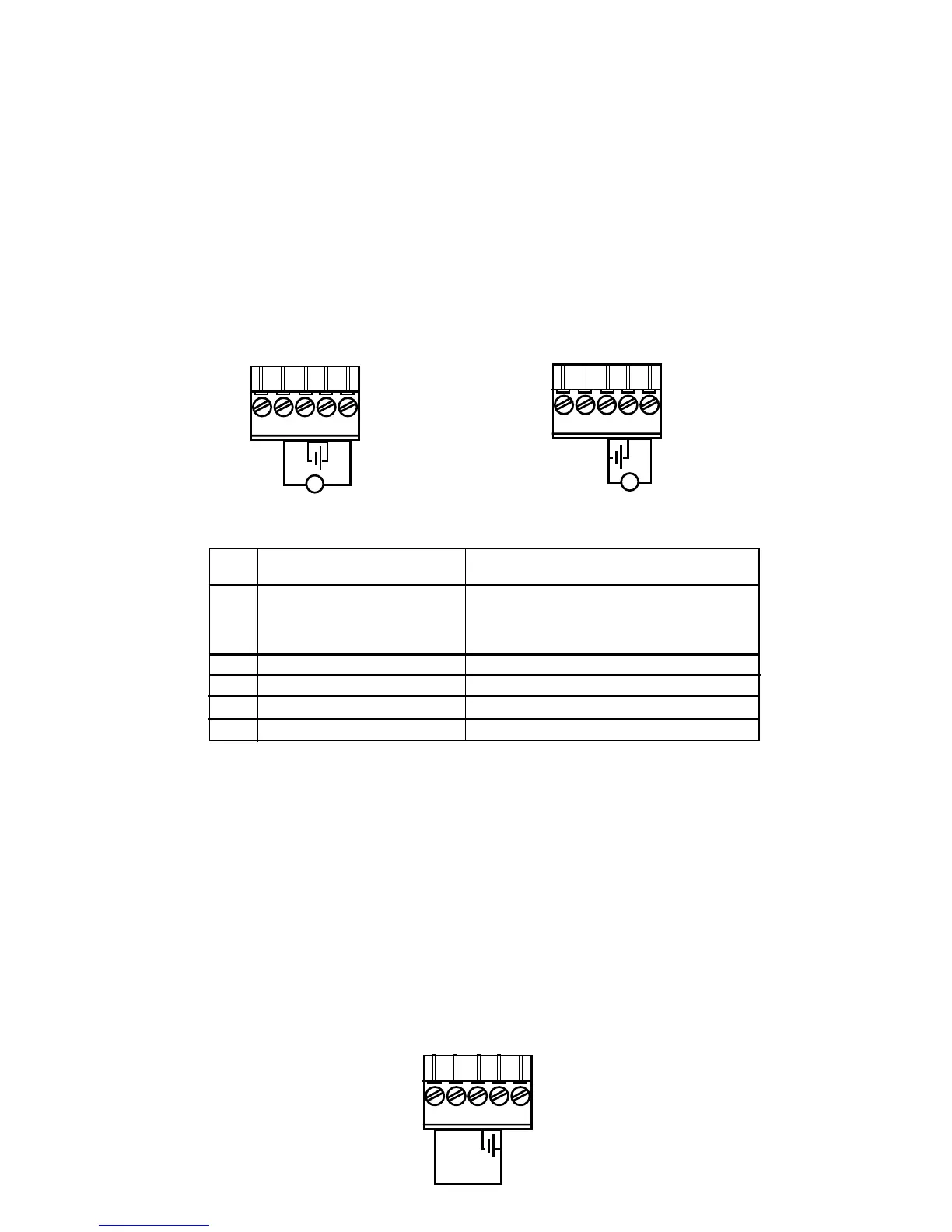
4.1 Voltage Output Units
The Model 278 barometric pressure transducer has five electrical
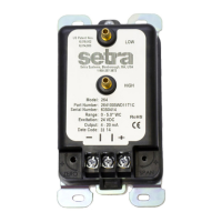
terminals available for wiring. This unit can be wired as a 4 wire (Fig. 1) or
3 wire (Fig. 2) device. Note:
Four wire connection is recommended to
avoid the voltage drop in the negative power line, which can affect
the accuracy of the pressure measurement.
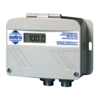
4.2 Adjustment for Continuous Operation
The Model 278 has two operating modes: normal (operating mode) and shut-
down (sleep mode). The unit is shipped in sleep mode (shutdown). To change
to normal operation mode, an external trigger voltage is needed so that the
transducer can wake up and measures pressure. For continuous operation, the
“External Trigger”, terminal 1, can also be wired with a jumper (external wire, not
provided) to the supply, terminal 4, (see Figure 3).
1 EXT TRIG External Trigger Signal
0 VDC Sleep Mode
3-28 VDC Operating Mode
2 AGND* Analog Signal Ground
3 GND* Supply Ground (Negative Power)
4 SUPPLY Supply (Positive Power)
5 VOUT Voltage Output
*Both grounds (AGND and GND) are in the same electrical potential in the
transducer.
Terminal
Function
No.
Figure 1
Figure 2
1 2 3 4 5
1 2 3 4 5
Four Wire Connection
Three Wire Connection
V
V
1 2 3 4 5
Figure 3