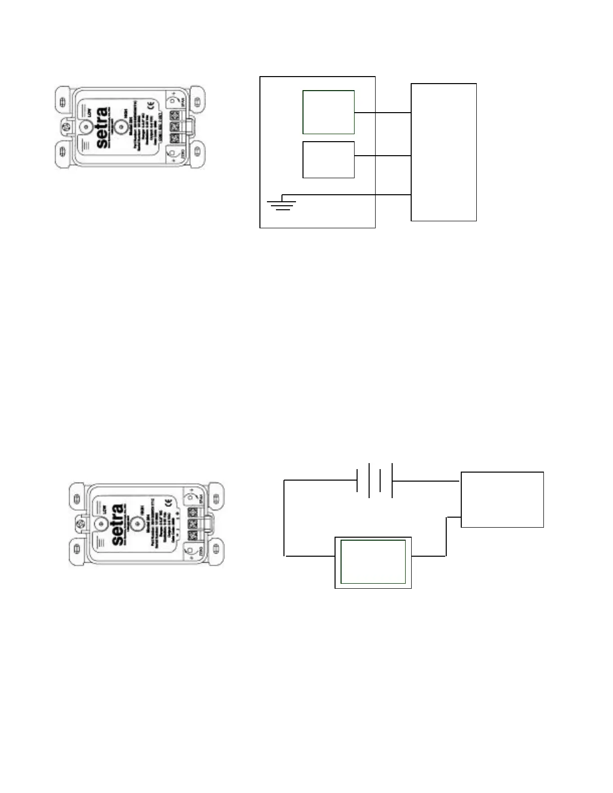
Voltage Circuit Diagram
Diagram 1 Diagram 2
+EXC Connect to positive terminal of 9-30 VDC Power Supply
+OUT Connect to positive terminal of Control or Pressure Monitor
COM Connect as the reference for power supply and output signal
3.2 Current Output Units
The Model DPT264 is a two-wire loop-powered 4 to 20 mA current output unit and delivers rated current
into any external load of 0 to 800 ohms. These terminals have the designation of + and – (see Diagram 3).
The current flows into the + terminal and returns back to the power supply through the – terminal (see
Diagram 4). The power supply must be a DC voltage source with a voltage range between 9 and 30
measured between the + and – terminals. The unit is calibrated at the factory with a 24 VDC loop supply
voltage and a 250ohm load.
Current Circuit Diagram
Diagram 3 Diagram 4
4.0 CALIBRATION
The DPT264 transducer is factory calibrated and should require no field adjustment. Generally, the mounting
position will have a zero effect on ranges below 1” WC. Whenever possible, any zero and/or span offsets should be
corrected by software adjustment in the user’s control system. However, both the zero and span adjustments are
accessible either on the front of the unit or by removing the optional conduit enclosure. The DPT264 transducer is
calibrated in the vertical position at the factory.
Readout
or
DAS
Power
Supply
Model
DPT264
OUT
EXC
COM
DPT264
9 to 20 VDC
Current
Monitoring
Device
+
–
 Loading...