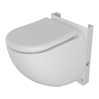
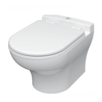
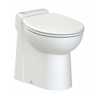
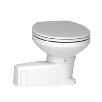
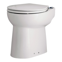
DESCRIPTION
SANICOMPACT
®
is a WC specially designed with an integral
pump/macerator. SANICOMPACT
®
is for domestic use.
Installed and used correctly, SANICOMPACT
®
will give
consistent and reliable service.
Please note the following warning signs:
" " Possible danger to personnel,
" " Warning of possible electrical hazard.
"WARNING" This is a general warning that failure to
follow instructions could result in poor functioning
of the unit.
OPERATION
SANICOMPACT
®
is operated by an electronic program.
It has 2 functions:
• It will macerate the WC waste and pump it away
to the drain: a push of the button will set in motion
the 25 second cycle to the above.
• It will pump away the waste water from a washandbasin.
In this case, the motor will activate automatically when
the water enters.
1
LIST OF ACCESSORIES INCLUDED
2
DIMENSIONS
3
TECHNICAL DATA
Applications
discharge of a WC
discharge of a washbasin (option)
Type
CS40 or CLV50
Maximum Vertical Pumping 3 m
Voltage 220-240 V
Frequency 50 Hz
Normal Power Rating 800 W
Maximum current consumption 2,6 A or 4,3 A
Electric Class I
Degree of protection IP44
Maximum water temperature 35°C
Net Weight C3 28,6 Kg
C5 29,0 Kg
C6 26,5 Kg
C43 23,2 Kg
C48 25,4 Kg
C4 22,0 Kg
WARNING: Only installations conforming to the above
specifications are acceptable.
4
PERFORMANCE CURVE
5
INSTALLATION
ATTACHING THE TOILET TO THE FLOOR
Find a suitable location, place the SANICOMPACT
®
on the
floor. Mark the perimeter of the bowl on the floor and mark
where the bracket screws will be, (rear screw holes).
Remove the bowl. Measure 5/8 inch (15 mm) inwards from
the line and mount the L-brackets on the floor.
Note: To reduce noise level when the toilet is installed on a
hard floor, you may want to insert an insulating material
between the floor and the bowl.
6a
6
CONNECTION OF THE DISCHARGE
1 - Push the plastic insert and rubber non return flap
down into the rubber discharge pipe until it is flush with
the lip.
2 - Point the non-return valve flap so that it opens in the
direction of flow of the discharge. Now place the
discharge elbow over the flap assembly.
3 - Secure the base of the elbow to the discharge pipe
and non-return valve flap assembly with the jubilee clip
provided .
Connect the 32 mm discharge pipework to the other
end and secure with jubilee clip .
4 - Warning: Ensure that you do not twist the discharge
pipework inside the unit.
5 - Warning: The horizontal portion of the discharge pipe
should be installed in a gravity flow, (1/4 inch to 1 foot).
Avoid any low parts in the discharge pipe.
6 - Warning: Protect pipes against freezing with appropriate
insulation. If the toilet is installed in an unheated location
during freezing periods protect it as follows:
• Shut off the water supply,
• Activate one cycle without water,
• Pour antifreeze in the bowl (2 litres),
• Flush the toilet.
7 - Warning: Any bends in the discharge pipe run should be
smooth radius bends. If using plastic pipe two 45 degree
offsets can be used to form a smooth bend.
8 - Note: We would recommend that a drain-off point is
installed to allow the discharge pipework to be drained
down before any service work.
9 - Note: To avoid siphoning, install a an anti-siphon valve
at the high point of the installation.
CONNECTION OF A WASH BASIN (OPTION)
If your SANICOMPACT
®
is equiped to receive the waste
water from a wash basin (Warning: special order).
Make the connection as shown on fig. to .
CONNECTION TO THE WATER SUPPLY
Connect the water supply hose to a shut off valve
Caution: The quality of the rinsing of the bowl depends on
the water pressure.
WARNING: for a correct rinsing, the water pressure should
be at least 25 PSI (1,7 bars).
Note: In an area where water is not pure (dirty, sandy), we
advise you to add a filter between the shut off valve and the
toilet to prevent clogging of the solenoid valve.
CONNECTION TO THE ELECTRICAL SUPPLY
The electrical installation should be carried by a
qualified person.
All wiring must conform to BS7671, 1992 requirements for
electrical installation. The unit requires a 220/240 V single
phase AC 50 Hz supply (UK specification). Do not connect
the unit to a conventional plug and socket. The unit should
be connected to a fully earthed electrical supply (class 1).
It must be wired into an unswitched fused fixed wiring
connector protected by a 5 amp fuse and a residual current
detector (30 mA). This connection must be used exclusively
for supplying the unit.
The wires in the mains lead are coloured in accordance
with the following code:
Brown – Live
Blue – Neutral
Green/Yellow – Earth
6e
6d
31
6c
D
C
I
H
6b
UK
Fully illustrated step by step instructions are
downloadable on www.saniflo.co.uk
 Loading...