I
GENERAL DESCRIPTION
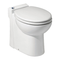
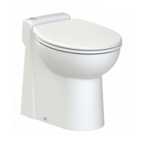
The SANICOMPACT
®
4 is a combination of
a floor-mounted vitreous china toilet with a
built-in macerating and pump system.
The SANICOMPACT
®
4 is meant to be
installed in residential applications and can
be adapted to discharge gray water from
a sink.
The SANICOMPACT
®
4 is comprised of two
major components: the china toilet body
and the macerating/pump unit in the base
of the toilet.
NORMAL OPERATING CYCLE
SANICOMPACT
®
4 is controlled by an
electronic program with two functions.
•
It has a macerating and pumping function.
To begin press on either side of the push
button (light grey: small flush, dark grey:
large flush) integrated to the bowl.
• The pump cycle cleans the washbasin
waste. This is an automatic operation
that will activate as long as water from
the washbasin enters the unit.
V
INSTALLATION
A
ATTACHING THE TOILET TO
THE FLOOR
After installing the water supply line and
the drain hose, place the SANICOMPACT
®
4
so that it is aligned with the piping.
Mark the perimeter of the base on the
floor with a pencil. Mark the fixing holes
of the bowl on the floor. Remove the
device. Measure 3/8 inch (1cm) inwards
from the crossing of the fixing holes; this
measurement marks the location of the
back of the plastic stirrup that will rest on
the inside of the porcelain bowl. Mark and
drill the holes. If the unit is installed on a
concrete or stone floor, drill two 5/16 inch
holes (8mm) at a depth of about 2 inches
(50mm) and insert the dowels. In the case
of installation on a wooden floor, drill a
guide hole for # 10 wood screws. Do not
over tighten the screws as the porcelain
base may crack.
B
CONNECTION OF THE
DISCHARGE ELBOW
1. Fully insert the elbow
F
in the end of
the rubber waste tube, after turning it
to face in the desired direction.
2. Fix the base of the elbow
F
and
tighten it on the rubber waste tube
with a clamp
G
.
3. Connect the sleeve
F
to the end of the
elbow with the clamp
G
.
If needed, cut off the end of the sleeve to
adapt it to the diameter of the discharge
line. Connect the 1” wastepipe into the
sleeve and secure with clamp
H
.
4. Warning: Ensure that you do not twist
the discharge pipework inside the unit.
IMPORTANT: Protect pipes against
freezing with appropriate insulation.
If the toilet is installed in an unheated
location during freezing periods protect
it as follows:
• Shut off the water supply,
• Activate one cycle without water,
• Pour antifreeze in the bowl (2 liters),
• Flush the toilet.
IMPORTANT: Any bends in the discharge
pipe run should be smooth radius bends.
II
LIST OF PARTS SUPPLIED
See page 3.
III
DIMENSIONS
See page 6.
IV
PERFORMANCE CURVE AND
TECHNICAL DATA
See page 5
.
APPLICATION 1 WC +
sink
Maximum vertical
pumping
9 feet
Voltage 110-115 V
Frequency 60 Hz
Normal power rating 815 W
Maximum current
consumption
7.2 A
Maximum water
temperature
110° F
Electric class I
Degree of protection IP44
Net weight 64 lbs
Horse power 0.5 HP
WARNING: Only installations conforming to
the above specifications are acceptable.
Sanicompact®4
IMPORTANT ADDITIONAL INFORMATION
If using plastic pipe, if a sweeping 90 is
not available, use two 45 degree turns
to create a smooth bend.
When connecting the discharge pipe, it
is recommended to install a ball valve for
servicing purposes on the lowest point
of the vertical discharge.The connection
to the soil-stack should be made with
an approved TY fitting and should be
in accordance with your local plumbing
code.
Note: The connection should always be
done going into the top of the soil stack
to prevent any back pressure into the
discharge line from the unit.
C
INSTALLATION OF A SINK
See page 3.
To drain a sink into the SANICOMPACT
®
4, the sink hose (provided) would have
to be installed. Lay the SANICOMPACT
®
4 on its side and cut the nipple which
is situated on the motor cover that can
be seen through the back of the unit.
Connect the flexible sink hose and secure
it to the motor cover using a clamp. A
1-1/4” drain pipe coming from the sink
will connect to the other end of the sink
hose which should also be secured by
means of a clamp. Note that if the sink
is installed on the left hand side of the
bowl (while facing the front of the toilet),
it will be required to have additional
back room to create a loop into the sink
hose connection. As the discharge line
interferes with the sink hose connection,
this will only be required when the sink is
installed to the left of the bowl.
D
WATER SUPPLY CONNECTION
See page 5.
For the best possible flushing action,
the SANICOMPACT
®
4 needs to be
connected to a 1/2-inch water supply.
The SANICOMPACT
®
4 is supplied with
a supply hose. The copper end of this
supply tube will fit inside the 3/8 inch
compression end of a shut-off valve. Due
to the international distribution of our
product range, it may be possible that
the tip of the supply connector is metric.
EN
1
 Loading...