PAGE 9
PAGE 8
ASSEMBLY
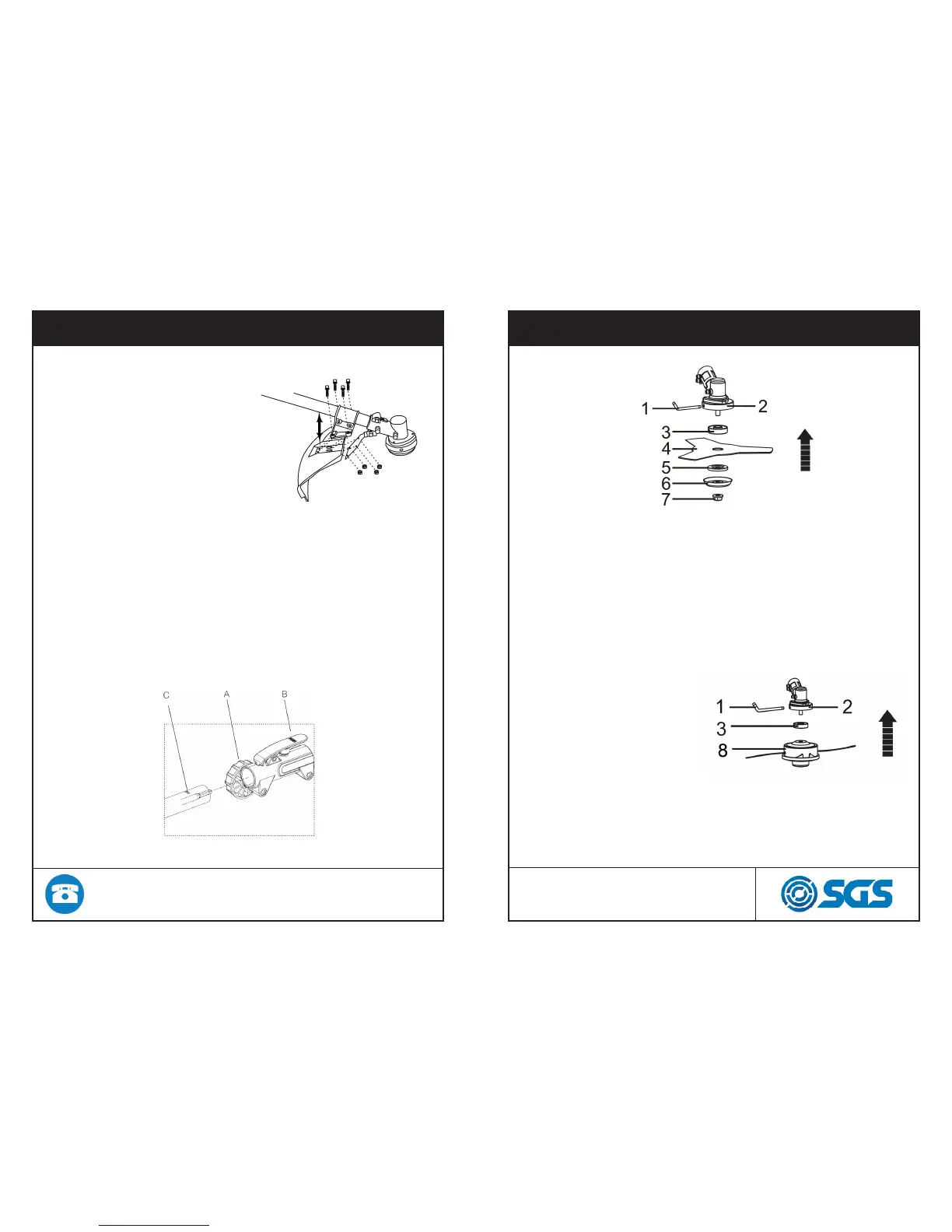
Fitting cutting attachment guard
Attach the cutting attachment
with the bolts combined
to the cutting attachment,
as illustrated to the right
Connecting the shaft
To connect the working shaft to the main shaft with a coupler
1. Loosen the Locking Knob (A) counterclockwise so the working
shaft can be inserted into the tube coupler.
2. Press the Push Button(B) and gently rotate the working shaft
back and for th while inserting to make sure the drive shafts
placed in position.
3. Release the Push Button to lock the hole (C) of the working
shaft tube. The Push Button is connected to a spring-loaded
detent that can snap the working tube in position
4. Turn the Locking Knob clock-wise to secure the connection.
ASSEMBLY
Installing blade
1. Insert the allen key (1) into the of the gear case (2) and
plate (3) so as to fasten the axle.
2. Mount the blade (4) and the washer (5) onto the axle.
3. Mount the washer (6) and the nut (7). Fasten tightly anti
clockwise.
Installing trimmer head
1. Insert the allen key (1)
into the hole of gear case
(2), and plate (3) so as to
fasten the axle.
2. Mount the trimmer head
(8), by turning it anti-clock-
wise.
3. Fasten the trimmer head
(8), tightly before use.