1
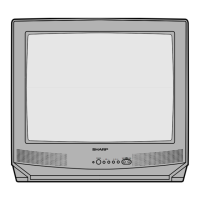
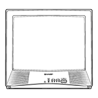
19R-M100
COLOR TELEVISION
Chassis No. SN-010
In the interests of user-safety (Required by safety regulations in some countries) the set should be restored to its
original condition and only parts identical to those specified should be used.
» ELECTRICAL SPECIFICATIONS .........................................................................................................1
» IMPORTANT SERVICE SAFETY PRECAUTION .................................................................................2
» LOCATION OF USER'S CONTROL .....................................................................................................4
» INSTALLATION AND SERVICE INSTRUCTIONS................................................................................5
» CHASSIS LAYOUT ............................................................................................................................. 11
» BLOCK DIAGRAM ..............................................................................................................................12
» SCHEMATIC DIAGRAMS ...................................................................................................................13
» PRINTED WIRING BOARD ASSEMBLIES ........................................................................................18
» REPLACEMENT PARTS LIST ............................................................................................................21
» PACKING OF THE SET ......................................................................................................................27
Page
SHARP CORPORATION
This document has been published to be used for after
sales service only.
The contents are subject to change without notice.
CONTENTS
SERVICE MANUAL
POWER INPUT.................................................... AC 120 V, 60 Hz
POWER RATING ................................................................... 69 W
PICTURE SIZE ........................................... 1,194cm
2
(185sq inch)
CONVERGENCE ............................................................. Magnetic
SWEEP DEFLECTION .................................................... Magnetic
FOCUS ............................................... Hi-Bi-Potential Electrostatic
INTERMEDIATE FREQUENCIES
Picture IF Carrier Frequency ..................................... 45.75 MHz
Sound IF Carrier Frequency...................................... 41.25 MHz
Color Sub-Carrier Frequency .................................... 42.17 MHz
(Nominal)
AUDIO POWER
OUTPUT RATING ..................................................... 1 W (RMS)
ELECTRICAL SPECIFICATIONS
SPEAKER
SIZE ...................................................................... 8 cm (Round)
VOICE COIL IMPEDANCE ............................ 32 ohm at 400 Hz
ANTENNA INPUT IMPEDANCE
VHF/UHF.....................................................75 ohm Unbalanced
TUNING RANGES
VHF-Channels...............................................................2 thru 13
UHF-Channels ............................................................14 thru 69
CATV Channels ...........................................................1 thru 125
(EIA, Channel Plan U.S.A.)
Specifications are subject to change without
prior notice.
MODEL
19R-M100
(
SREC
)
S11O219R-M100
P
O
W
E
R
V
O
L
C
H
V
I
D
E
O
A
U
D
I
O
I
N
M
E
N
U
1st. Edition