EasyManua.ls Logo

Sharp 19C140 - 19" CRT TV - User Manual

Sharp 19C140 - 19" CRT TV
24 pages
Print Icon
To Next Page IconTo Next Page
Loading...
COLOR TELEVISION
Chassis No. CD-A
In the interests of user-safety (Required by safety regulations in some countries) the set should be restored to its
original condition and only parts identical to those specified should be used.
» ELECTRICAL SPECIFICATIONS......................................................................................................... 1
» IMPORTANT SERVICE SAFETY PRECAUTION ................................................................................. 2
»LOCATION OF USER'S CONTROL.....................................................................................................4
»INSTALLATION AND SERVICE INSTRUCTIONS................................................................................5
»CHASSIS LAYOUT............................................................................................................................10
»BLOCK DIAGRAM.............................................................................................................................11
»SCHEMATIC DIAGRAMS..................................................................................................................12
»PRINTED WIRING BOARD ASSEMBLIES........................................................................................15
»REPLACEMENT PARTS LIST...........................................................................................................18
»PACKING OF THE SET.....................................................................................................................23
Page
SHARP CORPORATION
This document has been published to be used for after
sales service only.
The contents are subject to change without notice.
CONTENTS
SERVICE MANUAL
POWER INPUT................................120 V AC 60 Hz
POWER RATING .............................................69 W
PICTURE SIZE.......................1,194cm
2 (185sq inch)
CONVERGENCE........................................Magnetic
SWEEP DEFLECTION................................Magnetic
FOCUS...........................Hi-Bi-Potential Electrostatic
INTERMEDIATE FREQUENCIES
Picture IF Carrier Frequency ................. 45.75 MHz
Sound IF Carrier Frequency .................. 41.25 MHz
Color Sub-Carrier Frequency ................ 42.17 MHz
(Nominal)
ELECTRICAL SPECIFICATIONS
AUDIO POWER
OUTPUT RATING...........1.0 W (at 10% distortion)
SPEAKER
SIZE .................................................. 8 cm (Round)
VOICE COIL IMPEDANCE...........8 ohm at 400 Hz
ANTENNA INPUT IMPEDANCE
VHF/UHF................................ 75 ohm Unbalanced
TUNING RANGES
VHF-Channels.......................................... 2 thru 13
UHF-Channels........................................ 14 thru 69
CATV Channels ...................................... 1 thru 125
(EIA, Channel Plan U.S.A.)
Specifications are subject to change without
prior notice.
MODELS
19C140
19C140
Question and Answer IconNeed help?

Do you have a question about the Sharp 19C140 - 19" CRT TV and is the answer not in the manual?

Summary

Electrical Specifications

Service Safety Precautions

General and High Voltage Safety

General warnings, high voltage, picture tube, and X-radiation safety guidelines.

Pre-Return Checks and Component Safety

Final safety checks and guidelines for safety-related components.

Location of User Controls

Front Panel Controls

Description of controls located on the front panel of the TV.

Remote Control Functions

Explanation of the functions of the basic remote control.

Installation and Service Instructions

Circuit Protection

Details on the receiver's circuit protection fuse.

X-Radiation Protector Circuit Test

Procedure to test the X-radiation protection circuit.

High Voltage Check

Procedure for checking the high voltage output.

Service Adjustment Procedures

Entering and Exiting Service Mode

Instructions on how to access and exit the service mode.

Service Adjustment Selection

Steps for selecting and adjusting service parameters.

Service Adjustment Items

Picture and Color Adjustments

Adjustments for picture quality, tint, color, brightness, and sharpness.

Phase and Sweep Adjustments

Adjustments for vertical/horizontal phase, RF AGC, and VCO.

Colorimetry and Control Adjustments

Adjustments for colorimetry, trap, balance, and position controls.

System and Option Adjustments

Adjustments for system settings, energy saving, OSD, tuner, and options.

Detailed Service Adjustments

VCO and RF AGC Adjustment

Procedures for adjusting VCO and RF AGC.

Screen and White Balance Adjustment

Procedures for screen and white balance adjustments.

Sub-Picture, Tint, and Color Adjustment

Procedures for sub-picture, tint, and color adjustments.

Description of Schematic Diagram

Notes for Schematic Diagram

Explanations of units, resistor/capacitor notations, and ground symbols.

Voltage Measurement Conditions

Conditions and procedures for measuring DC voltages.

Waveform Measurement Conditions

Conditions and procedures for measuring waveforms.

Chassis Layout

PWB-B Layout

Layout diagram of Printed Wiring Board B.

PWB-A Layout

Layout diagram of Printed Wiring Board A.

Block Diagram

PWB-A Block Diagram

Block diagram of Printed Wiring Board A components and connections.

PWB-B Block Diagram

Block diagram of Printed Wiring Board B components and connections.

Cold and Hot Side Components

Identification of cold and hot side components in the block diagram.

Main Unit Schematic Diagram

Main Unit Schematic

Schematic diagram for the main unit of the television.

CRT Unit Schematic Diagrams

CRT Unit PWB-A Schematic

Schematic diagram for the CRT Unit's PWB-A.

CRT Unit PWB-B Schematic

Schematic diagram for the CRT Unit's PWB-B.

Printed Wiring Board Layouts

PWB-A: Main Unit Wiring Side

Wiring side layout of the PWB-A for the main unit.

Printed Wiring Board Layouts (Continued)

PWB-A: Main Unit Chip Parts Side

Chip parts side layout of the PWB-A for the main unit.

Printed Wiring Board Layouts (Continued)

PWB-B: CRT Unit Layouts

Wiring and chip sides layout of the PWB-B for the CRT unit.

Parts List

Parts Replacement Information

Information on replacing parts and how to order them.

Picture Tube Parts

List of replacement parts for the picture tube.

Integrated Circuits and Transistors

Lists of replacement integrated circuits and transistors.

Diodes and Packaged Circuits

Lists of replacement diodes and packaged circuits.

Parts List - Capacitors and Resistors

Capacitor List

List of replacement capacitors with their specifications.

Resistor List (Metal Oxide;Metal Film)

List of replacement resistors, specifying type and value.

Parts List - Resistors and Filters

Resistor List (Continued)

Continuation of replacement resistor listings.

Filters and Coils List

List of replacement filters and coils.

Transformer and Switch Parts

Lists of replacement transformers and switches.

Parts List - Jacks, Plugs, and Miscellaneous

Jack and Plug List

Lists of replacement jacks and plugs.

Miscellaneous Parts

List of various miscellaneous replacement parts.

CRT Unit Parts List

List of replacement parts specific to the CRT unit.

Miscellaneous and Packing Parts

Miscellaneous Parts (Continued)

Additional miscellaneous replacement parts.

Packing Parts

List of packing materials for the product.

Cabinet Parts

List of replacement cabinet components.

Supplied Accessories

List of accessories supplied with the product.

Packing of the Set

Packing Materials

Components and materials used for packing the set.

Packing Procedure

Steps for taping and stapling the packing case.

Overview

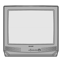
This document is a service manual for the Sharp 19C140 color television, providing comprehensive information for qualified service technicians to ensure safe and effective maintenance and repair. It outlines the device's functionality, key usage features, and detailed maintenance procedures, emphasizing safety and adherence to original specifications.

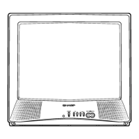
The Sharp 19C140 is a color television designed for home entertainment, offering standard video and audio playback capabilities. Its primary function is to display television broadcasts and external video sources, providing a visual and auditory experience for the user. The television is equipped with a conventional picture tube for image display and an integrated audio system for sound output.

Usage Features:

The television offers a user-friendly interface with controls located on both the front panel and a remote control unit.

  • Front Panel Controls:

    • Power: A button to turn the television on and off.
    • Volume Up/Down: Buttons to adjust the sound level, increasing or decreasing it as desired.
    • Channel Up/Down: Buttons to navigate through television channels, selecting the next higher or lower channel.
    • Video/Audio In Terminals: These terminals allow users to connect external video and audio sources, expanding the television's functionality beyond broadcast reception.
  • Basic Remote Control Functions: The remote control provides extended functionality and convenience for operating the television from a distance.

    • Power: Similar to the front panel, this button toggles the television's power.
    • Input: This button allows users to switch between external video input mode and TV mode, facilitating the use of connected devices.
    • Remote Keypad: A numerical keypad (0-9) enables direct access to any channel.
    • Flashback: This feature allows the user to quickly return to the previously viewed channel.
    • Volume Up/Down: These buttons control the sound level and also serve to change or select TV adjustments when in menu mode.
    • Channel Up/Down: These buttons select the next higher or lower channel and move the selection mark within the MENU screen.
    • Mute: This button mutes the sound, and pressing it again restores the sound. When sound is muted, "CLOSED CAPTION" may appear.
    • Menu: This button accesses the main menu for various settings and adjustments, and pressing it again exits the main menu.
    • Display: This button temporarily displays the receiving channel for 4 seconds and removes the display when pressed again. It also temporarily displays the receiving channel when in Closed Caption mode.

Maintenance Features:

The service manual provides detailed instructions for qualified service technicians to ensure the television's longevity, safety, and optimal performance.

  • Important Service Safety Precaution: This section highlights critical safety measures, including disconnecting AC power before servicing, awareness of semiconductor heat sinks, and understanding the two ground systems (non-isolated hot ground and isolated ground) to prevent electrical shock. It also emphasizes the use of an isolation transformer and the importance of replacing fuses with identical types for fire protection.
  • Servicing of High Voltage System and Picture Tube: Specific precautions are outlined for handling the high voltage system and picture tube, such as removing static charge, using shatterproof goggles, and replacing the picture tube with the same type for continued safety. It explicitly warns against lifting the picture tube by the neck.
  • X-Radiation and High Voltage Limits: This section stresses the importance of monitoring high voltage to prevent X-radiation, which can occur if the voltage exceeds specified levels. Technicians are required to use an accurate high voltage meter and ensure the high voltage regulator operates correctly.
  • Before Returning the Receiver (Fire & Shock Hazard): A series of safety checks are mandated before returning the television to the user. These include inspecting lead dress, protective devices, and checking for leakage current using a specific test procedure with an AC voltmeter. Any current exceeding 0.5 milliamp indicates a potential shock hazard requiring corrective action.
  • Safety Notice: This notice emphasizes that many electrical and mechanical parts have special safety-related characteristics, identified by "A" and shaded areas in the manual. Replacement parts must be identical to those used in the original circuit to prevent shock, fire, X-radiation, or other hazards.
  • Installation and Service Instructions:
    • Circuit Protection: The receiver is protected by a 4.0A fuse (F701) on PWB-A.
    • X-Radiation Protector Circuit Test: Detailed steps are provided to test the X-Radiation protection circuit after servicing horizontal deflection, high voltage, or +B systems. This involves applying specific voltages and checking voltmeter readings to ensure proper operation.
    • High Voltage Check: Instructions for checking the high voltage, which is not adjustable but must be verified to be within safe design limitations. This involves connecting a high voltage meter, operating the receiver for 15 minutes, and entering service mode to check the voltage at approximately 26.0kV (at zero beam).
  • Service Adjustment Procedures: The manual outlines a systematic approach to service adjustments, particularly for bus data converted to analog signals by the D/A converter circuit.
    • Entering and Exiting Service Mode: Instructions for entering service mode by simultaneously pressing the Vol-up and Ch-up buttons while plugging in the AC cord, and exiting by pressing the power button.
    • Service Number Selection: How to select specific adjustment numbers ("S01" to "OP") using the Ch-up or Ch-down buttons.
    • Data Number Selection: How to adjust data numbers using the Vol-up or Vol-down buttons.
    • Table - A (Adjustment Items): A table listing various adjustment items (e.g., Picture, Tint, Color, Brightness, Sharpness, Vertical Phase, Horizontal Phase, RF-AGC, Vertical Amp, VCO, Cut-Offs, Gains, TRAP, Balance, C.C. Position, Y-Mute, Energy Save Offset, D.D.E. Offset, OSD Setup, Tuner Setup, Option) with their initial values and ranges. It also notes that holding down CH-up/down buttons in service mode for more than 2 seconds will automatically write initial values to IC2101.
    • Table - B (Adjustment Necessity): This table indicates when adjustments are necessary after replacing specific parts like IC2001, IC201, IC2101, or the CRT. For instance, replacing IC2001 requires adjustment to compensate for characteristics of parts including IC201, while replacing IC2101 automatically writes initial values. CRT replacement requires adjustments related to the picture tube only.
    • Specific Adjustment Procedures: Detailed steps for various adjustments:
      • VCO Adjustment: Connecting a digital voltmeter to IC201 and adjusting data to read 2.2V.
      • RF AGC Adjustment: Adjusting data to eliminate noise or beat.
      • Screen Adjustment: Connecting a digital voltmeter to TP852 and TP853 on the CRT Unit, setting color level to minimum, turning off luminance signal, adjusting data to obtain 0.17 volts, adjusting master screen control, and then adjusting red, green, and blue cut-offs for a good grey scale.
      • White Balance Adjustment: Setting color level to minimum and adjusting "S14" and "S15" data for a good grey scale.
      • Sub-Picture Adjustment: Setting customer picture control to maximum and adjusting "S01" data for normal contrast.
      • Sub-Tint Adjustment: Setting customer tint control to center and adjusting "S02" data for normal flesh tones.
      • Sub-Color Adjustment: Setting customer color control to center and adjusting "S03" data for normal color level.
  • Description of Schematic Diagram: Provides notes on resistance units, resistor wattage, capacitor units, tolerance, and line isolated ground.
  • Voltage Measurement Conditions: Specifies conditions for measuring DC voltages (DVM connected to chassis ground, 120V AC line voltage, normal picture settings, and 1000μ V B & W or Color signal).
  • Waveform Measurement Conditions: Describes conditions for taking waveform photographs (standard gated color bar signal, proper tint setting) and identifies waveform check points.
  • Safety and X-Ray Related Parts: Clearly marks safety-related parts with "A" and shaded areas, and X-ray related parts with "MARK=".
  • Parts List: A comprehensive list of replacement parts, including tuners, integrated circuits, transistors, diodes, filters, coils, transformers, switches, ferrite beads, and miscellaneous parts. This list is crucial for ordering correct and identical replacement components.
  • Printed Wiring Board Assemblies: Diagrams of the PWB-A (MAIN Unit) and PWB-B (CRT Unit) from both wiring and chip parts sides, aiding technicians in component identification and placement.
  • Packing of the Set: Illustrates how the television is packaged, including polyethylene bag, wrapping paper, buffer material, and packing case, along with instructions for securing the packing case.

This manual serves as an indispensable guide for professional technicians, ensuring that the Sharp 19C140 television is maintained and repaired to the highest standards of safety and performance.

Sharp 19C140 - 19" CRT TV Specifications

General IconGeneral
Display TechnologyCRT
Screen Size19 inches
Aspect Ratio4:3
Power Consumption65W
Weight40.8 lbs
InputsComposite

Related product manuals