ADJUSTMENT PRECAUTIONS
This model's setting are adjusted in two different ways: through the I
2
C bus control and in the conventional
analog manner. The adjustments via the I
2
C bus control include preset-only items and variable data.
1. Setting the service mode by the microprocessor.
1. Short JA 137 & JA 138 for 1 second and release to switch to the service mode position, and the
microprocessor is in input mode. (Adjustment through the I2C bus control). (Use JWS Key to set as
well).
2. Press the CH DOWN / UP key on the remote controller to get ready to select the mode one by one.
3. Press the CH DOWN / UP key on the remote controller to select the modes reversibly one by one.
4. Using the VOLUME UP/ DOWN key on the remote controller, the data can be modified.
5. Short JA 137 & JA 138 for 1 second and release to switch to the normal mode (OFF) position, and the
microprocessor is in out of the service mode.
2. Factory Presetting.
1. Short JA 137 & JA 138, then turn on the main power and release to switch to the Service Mode position.
Initial values are automatically preset, only when a new EEPROM is used (Judge
with the first 4 bytes ).
2. The initial data are preset as listed in page 8, 9, & 10.
3. Make sure the data need modify or not (Initial data).
Note: Once the chassis has been assembly together and ready to be POWER ON for the FIRST TIME,
make sure to short JA137 & JA138 to switch to the service mode position first and then turn on the
main power switch (See 2-(1) above).
Precaution: If haven't done this initiation, it may possibly generate excessive Beam current.
3. For reference please check with memory map
(GA-1 Series type RH-iX3368CE N6)
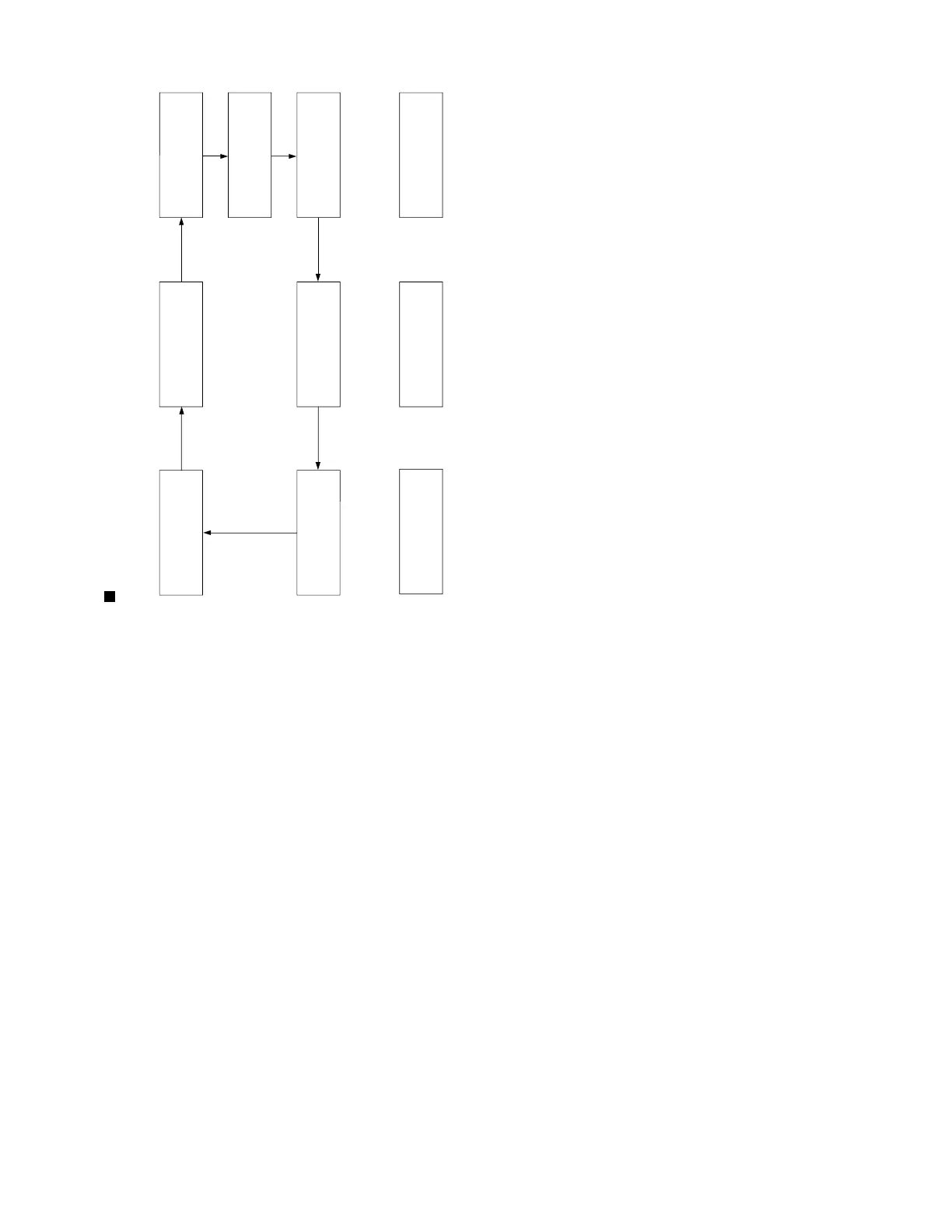
AGC &
GEOMETRIC
MODE
↓
AGC TAKE OVER POINT (AGC)
↓
VERTICAL SLOPE (V-LIN)
↓
VERTICAL AMP (V-AMP)
↓
VERTICAL SHIFT (V-CENT)
↓
HORIZONTAL SHIFT (H-CENT)
↓
EAST-WEST WIDTH (H-SIZE)
↓
HORIZONTAL PARALLELOGRAM (EW//)
↓
EAST-WEST PARABOLA/WIDTH (PARA)
↓
EAST-WEST UPPER COR. PB (LOR(U))
↓
EAST-WEST LOWER COR. PB (COR(L))
↓
EAST-WEST TRAPEZIUM (TRAPE)
↓
HORIZONTAL BOW (HB)
↓
S-CORRECTION (S-COR)
WHITE POINT
ADJ.
MODE
↓
W.P RED STD. W.T. (DRI-RS)
↓
W.P. GREEN STD. W.T.(DRI-GS)
↓
W.P.BLUE STD. W.T. (DRI-BS)
↓
W.P. RED WARM W.T.(DRI-RC)
↓
W.P. GREEN WARM W.T.(DRI-GC)
↓
W.P. BLUE WARM W.T.(DRI-BC)
↓
W.P. RED COOL W.T.(DRI-RW)
↓
W.P. GREEN COOL W.T.(DRI-GW)
↓
W.P. BLUE COOL W.T. (DRI-BW)
SUB
ADJ.
MODE
↓
MAX VOLUME (SUB-VOL)
↓
SUB CONTRAST (SUB-CON)
↓
SUB COLOUR (SUB-COL)
↓
SUB BRIGHTNESS (SUB-BRI)
↓
SUB TINT (SUB-TINT)
↓
SUB SHARPNESS (SUB-SHP)
↓
MAX HOTEL VOLUME (HTL-VOL)
↓
HOTEL PROGRAM NO(HTL-PRG)
↓
OSD RGB REFERENCE (RGB)
↓
BLACK LEVEL OFFSET R(CUT-R)
↓
BLACK LEVEL OFFSET B(CUT-B)
↓
CATHODE DRIVE LEVEL(CDL)
FORWARD : CH DOWN KEY
REVERSE : CH UP KEY
* ( ) means OSD display.
FORWARD : CH DOWN KEY
REVERSE : CH UP KEY
AGC &
GEOMETRIC
MODE
WHITE POINT
ADJ.
MODE
SUB
ADJ.
MODE
Y-DELAY
ADJ.
MODE
MISC.
OPTION
MODE
IC
OPTION
MODE
OFFSET
ADJ.
MODE