EasyManua.ls Logo

Sharp 20N-S100S User Manual

Sharp 20N-S100S
29 pages
To Next Page IconTo Next Page
Page #1 background imageLoading...
Page #1 background image
1
20N-S100S
CN20S10
COLOR TELEVISION
Chassis No. SN-000
In the interests of user-safety (Required by safety regulations in some countries) the set should be restored to its
original condition and only parts identical to those specified should be used.
S20W920N-S100
» ELECTRICAL SPECIFICATIONS .........................................................................................................1
» IMPORTANT SERVICE SAFETY PRECAUTION .................................................................................2
» LOCATION OF USER'S CONTROL .....................................................................................................6
» INSTALLATION AND SERVICE INSTRUCTIONS ................................................................................7
» CHASSIS LAYOUT .............................................................................................................................13
» BLOCK DIAGRAM ..............................................................................................................................14
» SCHEMATIC DIAGRAMS ...................................................................................................................15
» PRINTED WIRING BOARD ASSEMBLIES ........................................................................................20
» REPLACEMENT PARTS LIST ............................................................................................................23
» PACKING OF THE SET ......................................................................................................................29
Page
SHARP CORPORATION
CONTENTS
SERVICE MANUAL
POWER INPUT ..................................................... 120 V AC 60 Hz
POWER RATING ................................................................... 88 W
PICTURE SIZE ........................................... 1,240cm
2
(192sq inch)
CONVERGENCE ............................................................. Magnetic
SWEEP DEFLECTION .................................................... Magnetic
FOCUS ............................................... Hi-Bi-Potential Electrostatic
INTERMEDIATE FREQUENCIES
Picture IF Carrier Frequency ..................................... 45.75 MHz
Sound IF Carrier Frequency...................................... 41.25 MHz
Color Sub-Carrier Frequency .................................... 42.17 MHz
(Nominal)
AUDIO POWER
OUTPUT RATING ....................1.3W + 1.3W (at 10% distortion)
ELECTRICAL SPECIFICATIONS
SPEAKER
SIZE ...................................................................... 8 cm (Round)
VOICE COIL IMPEDANCE ............................ 32 ohm at 400 Hz
ANTENNA INPUT IMPEDANCE
VHF/UHF.....................................................75 ohm Unbalanced
TUNING RANGES
VHF-Channels...............................................................2 thru 13
UHF-Channels ............................................................14 thru 69
CATV Channels ...........................................................1 thru 125
(EIA, Channel Plan U.S.A.)
MODELS
20N-S100S
CN20S10
This document has been published to be used for after
sales service only.
The contents are subject to change without notice.
Specifications are subject to change without
prior notice.
MTS STEREO
Question and Answer IconNeed help?

Do you have a question about the Sharp 20N-S100S and is the answer not in the manual?

Sharp 20N-S100S Specifications

General IconGeneral
BrandSharp
Model20N-S100S
CategoryTV
LanguageEnglish

Summary

Important Service Safety Precautions

Warning and High Voltage Precautions

Essential safety guidelines for service, including X-ray limits and high voltage handling.

Before Returning the Receiver

Critical safety checks required before returning the unit to the user.

Safety Notice

Information on components with special safety characteristics and replacement guidelines.

Location of User's Control

Front Panel Controls

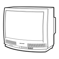
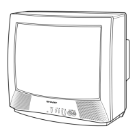
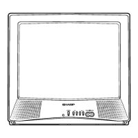
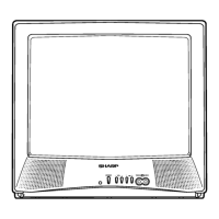
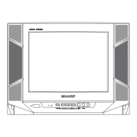
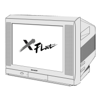
Identifies and explains the function of controls on the television's front panel.

Remote Control Functions

Details the operation of various buttons on the remote control.

Installation and Service Instructions

Circuit Protection

Information regarding the receiver's internal fuse and its role in circuit protection.

X-Radiation Protector Circuit Test

Procedure for verifying the proper operation of the X-radiation protection circuit.

High Voltage Check

Guidelines for checking the high voltage output for safety and optimal performance.

Service Adjustments

Service Mode and Categories

Steps to enter service mode and overview of adjustment categories like DEF, SIGNAL, FEATURE, FIX VALUE.

Adjustment Tables (FIX VALUE, DEF, SIGNAL)

Details of initial values and ranges for FIX VALUE, DEF, and SIGNAL adjustments.

FEATURE Adjustments

Details of initial values and ranges for FEATURE adjustments.

Specific Picture and Signal Adjustments

Procedures for RF AGC, Video Level, Screen, White Balance, Sub-Picture, Tint, Color, Brightness.

Vertical, MTS, and Caption Adjustments

Procedures for vertical geometry, MTS, and caption positioning.

Chassis Layout

Block Diagram

Schematic Diagrams

Description of Schematic Diagrams

Explanation of symbols, notes, and measurement conditions for schematic diagrams.

Waveforms

Visual representation of signal waveforms at key test points for troubleshooting.

Schematic Diagram: Main Unit

Schematic Diagram: CRT Unit

Schematic Diagram: MTS Module Unit

Printed Wiring Board Assemblies

PWB-A: MAIN Unit (Wiring Side)

Wiring layout diagram for the main unit's PWB-A.

PWB-A: MAIN Unit (Chip Parts Side)

Component layout diagram for the main unit's PWB-A chip side.

PWB-B: CRT Unit (Wiring Side)

Wiring layout diagram for the CRT unit's PWB-B.

PWB-B: CRT Unit (Chip Parts Side)

Component layout diagram for the CRT unit's PWB-B chip side.

PWB-C: MTS MODULE Unit (Wiring Side)

Wiring layout diagram for the MTS module unit's PWB-C.

PWB-C: MTS MODULE Unit (Chip Parts Side)

Component layout diagram for the MTS module unit's PWB-C chip side.

Parts List

Picture Tube Parts

List of replacement parts specifically for the picture tube assembly.

Integrated Circuits

List of integrated circuits used in the television, including part numbers.

Capacitors

A comprehensive list of capacitors with their specifications and part numbers.

Resistors

A comprehensive list of resistors with their specifications and part numbers.

Packaged Circuits, Filters, and Coils

Lists of packaged circuits, filters, and coils used in the unit.

Miscellaneous Parts

List of various other components like relays, fuses, jacks, and screws.

Cabinet Parts

List of replacement parts for the television's cabinet and external housing.

Packing of the Set

Related product manuals