EasyManua.ls Logo

Sharp 20MU14 User Manual

Sharp 20MU14
24 pages
To Next Page IconTo Next Page
Page #1 background imageLoading...
Page #1 background image
1
COLOR TELEVISION
Chassis No. CD-A
In the interests of user-safety (Required by safety regulations in some countries) the set should be restored to its
original condition and only parts identical to those specified should be used.
» ELECTRICAL SPECIFICATIONS......................................................................................................... 1
» IMPORTANT SERVICE SAFETY PRECAUTION ................................................................................. 2
»LOCATION OF USER'S CONTROL.....................................................................................................4
»INSTALLATION AND SERVICE INSTRUCTIONS................................................................................5
»CHASSIS LAYOUT............................................................................................................................10
»BLOCK DIAGRAM.............................................................................................................................11
»SCHEMATIC DIAGRAMS..................................................................................................................12
»PRINTED WIRING BOARD ASSEMBLIES........................................................................................15
»REPLACEMENT PARTS LIST...........................................................................................................18
»PACKING OF THE SET.....................................................................................................................23
Page
SHARP CORPORATION
This document has been published to be used for after
sales service only.
The contents are subject to change without notice.
CONTENTS
SERVICE MANUAL
POWER INPUT................................120 V AC 60 Hz
POWER RATING .............................................69 W
PICTURE SIZE.......................1,194cm
2 (185sq inch)
CONVERGENCE........................................Magnetic
SWEEP DEFLECTION................................Magnetic
FOCUS...........................Hi-Bi-Potential Electrostatic
INTERMEDIATE FREQUENCIES
Picture IF Carrier Frequency ................. 45.75 MHz
Sound IF Carrier Frequency .................. 41.25 MHz
Color Sub-Carrier Frequency ................ 42.17 MHz
(Nominal)
ELECTRICAL SPECIFICATIONS
AUDIO POWER
OUTPUT RATING...........1.0 W (at 10% distortion)
SPEAKER
SIZE .................................................. 8 cm (Round)
VOICE COIL IMPEDANCE...........8 ohm at 400 Hz
ANTENNA INPUT IMPEDANCE
VHF/UHF................................ 75 ohm Unbalanced
TUNING RANGES
VHF-Channels.......................................... 2 thru 13
UHF-Channels........................................ 14 thru 69
CATV Channels ...................................... 1 thru 125
(EIA, Channel Plan U.S.A.)
Specifications are subject to change without
prior notice.
MODELS
20MU14
20MU14
Question and Answer IconNeed help?

Do you have a question about the Sharp 20MU14 and is the answer not in the manual?

Sharp 20MU14 Specifications

General IconGeneral
Aspect Ratio16:9
Display TypeLED
USB Ports1
Built-in TunerYes
Screen Size20 inches
Display Size20 inches
Resolution1366 x 768

Summary

Electrical Specifications

Technical Specifications Overview

Details power, picture, IF, audio, tuning ranges, and impedance for the television.

Important Service Safety Precautions

General Safety and High Voltage Warnings

Covers circuit modification, power disconnect, shock hazards, isolation transformers, and X-ray limits.

Leakage Current Testing and Safety Notices

Details leakage current test procedure, safety-related parts identification, and replacement part guidelines.

Location of User Controls

Front Panel and Remote Control Functions

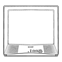
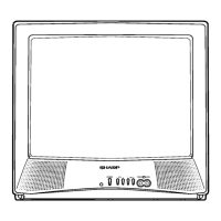
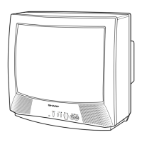
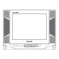
Identifies front panel controls and explains basic remote control operations and buttons.

Installation and Service Instructions

Circuit Protection and X-Radiation Test

Explains circuit protection fuse and procedure for testing the X-radiation protector circuit.

High Voltage Check and Service Mode

Details high voltage measurement procedures and how to enter/exit the service mode for adjustments.

Detailed Service Adjustments

Provides step-by-step instructions for various service adjustments like VCO, RF AGC, and White Balance.

Chassis Layout

Component Placement Diagram

Illustrates the physical layout of components on the main unit's PWB-A and PWB-B.

Block Diagram

System Functional Overview

Presents a functional block diagram of the television's internal systems and signal flow.

Schematic Diagrams

Main Unit and CRT Unit Schematics

Detailed circuit diagrams for the main unit and the CRT unit.

Printed Wiring Board Assemblies

PWB Layouts (Wiring and Chip Sides)

Shows the wiring and chip component layouts for the Main Unit and CRT Unit PWBs.

Replacement Parts List

Parts Identification and Ordering

Lists part numbers, descriptions, and codes for replacement components like ICs, transistors, and diodes.

Component Categories and Miscellaneous Parts

Details capacitors, resistors, switches, miscellaneous parts, packing parts, and accessories.

Packing of the Set

Packaging Procedure Diagram

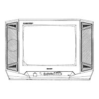
Illustrates the materials and steps involved in packing the television for shipment.

Related product manuals