21S-FX10F/10S/10N/10U
3 – 16
NO ADJUSTMENT POINT WAVEFORM OR OTHERS
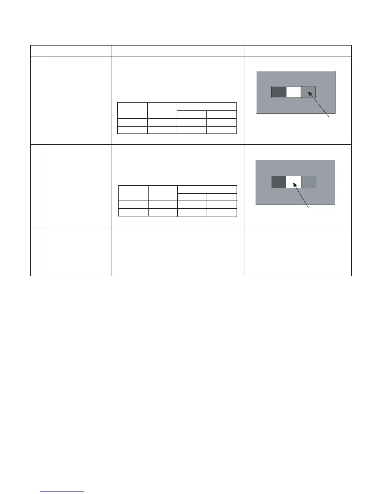
3
SUB-BRIGHTNESS
(to be done after
screen, white
balance adj)
(I2C BUS CONTROL)
ADJUSTMENT CONDITION / PROCEDURE
(1) In Window Pattern Signal condition.
(2) Using Minolta Color Analyzer CA-100,
let the gun point at Dark White position
(as attach drawing), adjust SUB-BRI Bus
data until :
WINDOW PATTERN SIGNAL
Dark White
4
SUB-CONTRAST
(to be done after
screen, white
balance adj,
sub-brightness adj)
(I2C BUS CONTROL)
(1) In Window Pattern Signal condition.
(2) Using Minolta Color Analyzer CA-100, let
the gun point at White position (as attach
drawing), adjust SUB-CON Bus data until :
White
WINDOW PATTERN SIGNAL
5
BEAM
CURRENT
CHECK
(1) Receive the "Monoscope Pattern" signal.
(2) Press R/C to set Picture NORMAL condition.
(3) Connect the DC miliammeter between TP 603
(+)&TP602(-)(Full Scale: 3mA Range).
(4) Beam current must be within : 1000 ± 100µA
Service Luminance
mode (cd/m2) Upper limit Lower limit
Enable 4.0 +0.5 -0.5
Disable 4.0 +2.5 -1.0
Service Luminance
mode (cd/m2) Upper limit Lower limit
Enable 150.0 +10 -10
Disable 150.0 +20 -10