21S-FX10F/10S/10N/10U
3 – 17
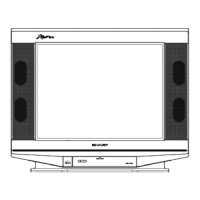
5. PAL CHROMA ADJUSTMENT
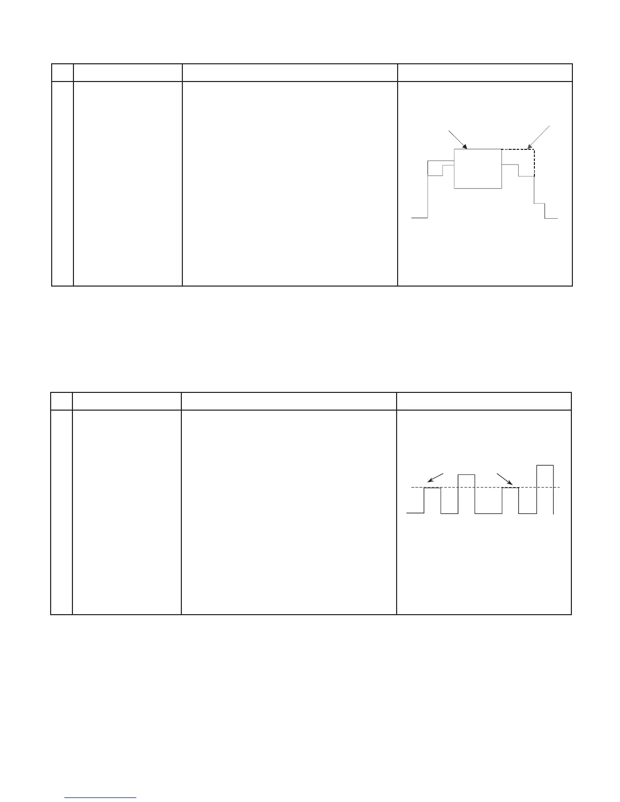
6. NTSC CHROMA ADJUSTMENT
NO ADJUSTMENT POINT WAVEFORM OR OTHERS
1
SUB COLOUR
(I2C BUS CONTROL)
ADJUSTMENT CONDITION / PROCEDURE
1. Receive the "PAL Split Color Bar" signal.
2. Make the image normal with the remote
controller.
3. Connect the oscilloscope to TP47R (R863)
RED-OUT.
Range : 500mV/Div (AC)
(Use Probe 10:1)
Sweep time : 10µsec/Div
4. Set the sub color adjustment mode with the
remote controller, and vary the sub color data
to make 100% W of the color bar and RED
at the same level for adjustment shown in
Fig. 1-1.
Cy G
W
100% WHITE
R
MgYB
Fig 1-1
NO ADJUSTMENT POINT WAVEFORM OR OTHERS
1
SUB-TINT
(I2C BUS CONTROL)
(to be done after
sub colour adj)
ADJUSTMENT CONDITION / PROCEDURE
(1) Receive the "NTSC 3.58 Colour Bar" signal
through AV IN from IWATSU SX1006 pattern
generator.
(2) Connect the oscilloscope to TP47B (R865)
BLUE-OUT
Range : 500mV/Div (AC)
(Use Probe 10:1)
Sweep time : 10µsec/Div
(3) Select the "SUB-TINT" item in the
ADJUSTMENT MODE.. Adjust the "SUB-
TINT" data to obtain the waveform shown
as Figure 1.2 (W and Mg same level)
Same Level
Fig 1-2
WY G R BCy Mg