1
25L-M100/180/S100/180
CL25M10,CL25S18
SERVICE MANUAL
COLOR TELEVISION
Chassis No. SN-91
In the interests of user-safety (Required by safety regulations in some countries) the set should be restored to its
original condition and only parts identical to those specified should be used.
S49F325L-M100
» ELECTRICAL SPECIFICATIONS........................................................................................................ 1
» IMPORTANT SERVICE SAFETY PRECAUTION ............................................................................... 2
» LOCATION OF USER'S CONTROL.................................................................................................... 6
» INSTALLATION AND SERVICE INSTRUCTIONS ............................................................................ 10
» CHASSIS LAYOUT ........................................................................................................................... 16
» BLOCK DIAGRAM ............................................................................................................................ 18
» SCHEMATIC DIAGRAMS ................................................................................................................. 20
» PRINTED WIRING BOARD ASSEMBLIES ....................................................................................... 38
» REPLACEMENT PARTS LIST .......................................................................................................... 41
» PACKING OF THE SET..................................................................................................................... 49
Page
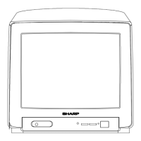
25L-S100/180
CL25S18
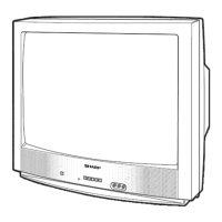
25L-M100/180
CL25M10
SHARP CORPORATION
This document has been published to be used for after
sales service only.
The contents are subject to change without notice.
CONTENTS
25L-M100/180, 25L-S100/180
CL25M10, CL25S18
MODELS
ELECTRICAL SPECIFICATIONS
POWER INPUT ................................................... 120 V AC 60 Hz
POWER RATING
25L-M100/180, CL25M10 ................................................. 105 W
25L-S100/180, CL25S18 .................................................. 110 W
PICTURE SIZE ........................................... 2,032cm
2
(315sq inch)
CONVERGENCE............................................................. Magnetic
SWEEP DEFLECTION .....................................................Magnetic
FOCUS ............................................... Hi-Bi-Potential Electrostatic
INTERMEDIATE FREQUENCIES
Picture IF Carrier Frequency ..................................... 45.75 MHz
Sound IF Carrier Frequency ...................................... 41.25 MHz
Color Sub-Carrier Frequency..................................... 42.17 MHz
(Nominal)
AUDIO POWER
25L-M100/180, CL25M10 ............... 1.3W (at 10% distortion and
Dual CH Operate)
25L-S100/180, CL25S18 .... 1.3W +1.3W (at 10% distortion and
Dual CH Operate)
SPEAKER
SIZE ...................................................................... 8 cm (Round)
VOICE COIL IMPEDANCE ............................. 32 ohm at 400 Hz
ANTENNA INPUT IMPEDANCE
VHF/UHF .................................................... 75 ohm Unbalanced
TUNING RANGES
VHF-Channels .............................................................. 2 thru 13
UHF-Channels ............................................................ 14 thru 69
CATV Channels .......................................................... 1 thru 125
(EIA, Channel Plan U.S.A.)
Specifications are subject to change without
prior notice.