11
32C240
32C241
Sub-Tint Adjustment
1. Receive the half color bar signal.
• RF INPUT (TU51)
2. Get into Y-Mute by R/C, or by setting the "V11" bus
data to "01".
3. Vary the "V02" bus data until the waveform becomes
as stated below.
Sub-Color Adjustment
1. Receive a good local channel.
2. Make sure the customer color control is set to center
position .
• RF INPUT (TU51)
3. Enter the service mode and select service adjustment
"V03".
4. Adjust "V03" data value to obtain a normal color level.
Focus Adjustment
1. Receive a good local channel.
2. Adjust the focus VR of the flyback transformer to make
the image as fine as possible.
C. C Display Position Adjustment
1. Receive the lion head pattern signal.
2. Select "EX2" to display the text box.
3. Adjust the "EX2" bus data to let the text box displayed
in the center.
Vertical-Size and Linearity Adjustments
1. Receive a good local channel.
2. Enter the service mode and select the service
adjustment "D03" for V-size.
3. Adjust the "D03" bus data to get the proper V-size.
4. For V-linearity adjustment, select data bus "D05" and
adjust to get the proper vertical linearity.
Note: Aging for 10 min before adjustment. After the
adjustment of V-center and V-size, re-
adjustment for this V-line.
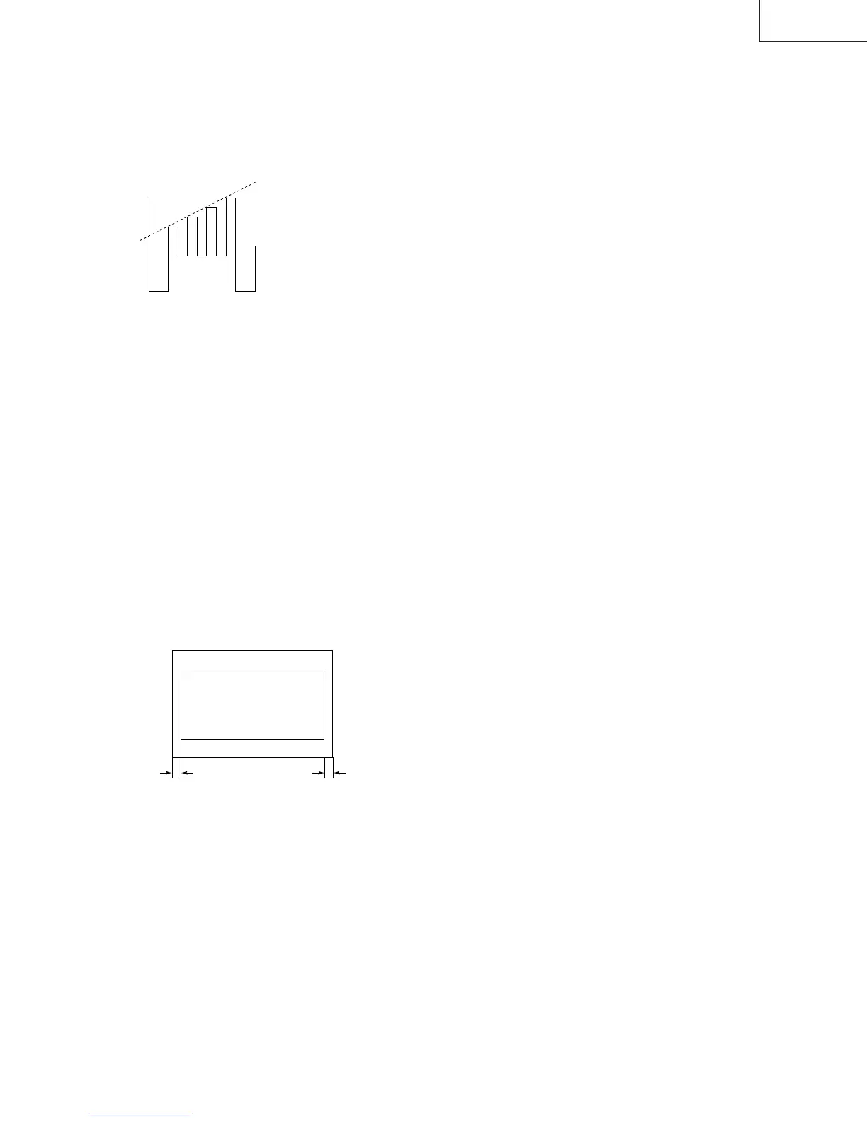
B-AMP Base waveform in step
(TP47B)
LEVEL
DISPLAY OF TEXT BOX
TEXT BOX
A
B
| A-B | / 2
SPEC INSPECTION:| A-B | / 2
<
=
5mm
Vertical Phase Adjustment
1. Enter the service mode and input "D01" data value
to "00h".
2. Adjust "D18" data value so that picture is centered.
Horizontal Position Adjustment
1. Receive a good local channel.
2. Enter the service mode and select the service
adjustment "D02".
3. Adjust "D02" data value so that picture is centered.
Horizontal-Size Adjustment
1. Receive a good local channel.
2. Enter the service mode and select the service
adjustment "D04" for H-size.
3. Adjust the "D04" bus data to get the proper H-size.
EW-Parabola
1. Receive a good local channel.
2. Enter the service mode and select the service
adjustment "D07" for EW parabola.
3. Adjust the "D07" bus data to get the proper vertical
straight line for both left and right side.
EW-Trapezium
1. Receive a good local channel.
2. Enter the service mode and select the service
adjustment "D08" for EW-Trapezium.
3. Adjust the "D08" bus data to get the best position
display.
Ë
MTS ADJUSTMENT
MTS Level Adjustment
1. Set the sound volume above 1.
Monoral signal: 400Hz, 100% modulation
2. Confirm "EX4" data is "5Ah".
3. Vary the "M01" bus data until the voltage to pin (39)
of IC3001 to become the value as stated below.
SETTING VOLTAGE
ADJ spec : 490±10mVrms
CHK spec: 490±20mVrms
Separation Adjustment
1. Input "SIGNAL 1" and vary the "M04" bus data to get
the minimun AC voltage to pin (39) of IC3001.
2. Input "SIGNAL 2" and vary the "M05" bus data to get
the minimun AC voltage to pin (39) of IC3001.
SIGNAL 1:
300Hz, 30% modulation, Lch only, NR-ON
SIGNAL 2: 3kHz, 30% modulation, Lch only, NR-ON
Note: SIGNAL 1 Adj. for widebando
SIGNAL 2 Adj. for spectral
Check the output of the speaker at the maximum
volume as stated below.
Confirmation spec:
ADJ spec: above 25 dB
CHK spec: above 20 dB