EasyManua.ls Logo

Sharp 32C241

Sharp 32C241
34 pages
To Next Page IconTo Next Page
Loading...
32C240
32C241
SHARP CORPORATION
This document has been published to be used for after
sales service only.
The contents are subject to change without notice.
COLOR TELEVISION
Chassis No. GB-3U (1W)
SERVICE MANUAL
S24O932C240//
In the interests of user-safety (Required by safety regulations in some countries ) the set should be restored to its
original condition and only parts identical to those specified should be used.
Page
» ELECTRICAL SPECIFICATIONS .........................................................................................................1
» IMPORTANT SERVICE SAFETY PRECAUTION .................................................................................2
» LOCATION OF USER'S CONTROL .....................................................................................................4
» INSTALLATION AND SERVICE INSTRUCTIONS................................................................................6
» SERVICE ADJUSTMENT ...................................................................................................................10
» CHASSIS LAYOUT .............................................................................................................................12
» BLOCK DIAGRAM ..............................................................................................................................13
» DESCRIPTION OF SCHEMATIC DIAGRAM & WAVEFORMS ..........................................................14
» SCHEMATIC DIAGRAMS ...................................................................................................................15
» PRINTED WIRING BOARD ASSEMBLIES ........................................................................................22
» REPLACEMENT PARTS LIST............................................................................................................25
» PACKING OF THE SET ......................................................................................................................33
CONTENTS
SPEAKER
SIZE ........................................................12 x 6 cm oval (2 pcs.)
VOICE COIL IMPEDANCE ............................ 16 ohm at 400 Hz
ANTENNA INPUT IMPEDANCE
VHF/UHF.....................................................75 ohm Unbalanced
TUNING RANGES
VHF-Channels...............................................................2 thru 13
UHF-Channels ............................................................14 thru 69
CATV Channels ...........................................................1 thru 125
(EIA, Channel Plan U.S.A.)
POWER INPUT ..................................................... 120V AC, 60 Hz
POWER RATING .................................................................. 135W
PICTURE SIZE .......................................... 3,073 cm
2
(476sq inch)
CONVERGENCE ............................................................. Magnetic
SWEEP DEFLECTION .................................................... Magnetic
FOCUS ............................................... Hi-Bi-Potential Electrostatic
INTERMEDIATE FREQUENCIES
Picture IF Carrier Frequency ..................................... 45.75 MHz
Sound IF Carrier Frequency...................................... 41.25 MHz
Color Sub-Carrier Frequency .................................... 42.17 MHz
(Nominal)
AUDIO POWER
OUTPUT RATING .............. 3.0W + 3.0W (at 10% distortion and
Dual CH Operate)
Specifications are subject to change without
prior notice.
ELECTRICAL SPECIFICATIONS
MODELS
32C240
32C241
32C24132C240
Question and Answer IconNeed help?

Do you have a question about the Sharp 32C241 and is the answer not in the manual?

Sharp 32C241 Specifications

General IconGeneral
BrandSharp
Model32C241
CategoryTV
LanguageEnglish

Summary

ELECTRICAL SPECIFICATIONS

SERVICE SAFETY PRECAUTIONS

General Warnings

Critical safety warnings for servicing procedures.

High Voltage and X-Radiation Safety

Precautions and limits regarding X-radiation and high voltage.

SAFETY NOTICES

USER CONTROL LOCATIONS

32 C240 Front Panel Controls

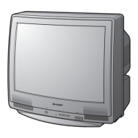
Identifies controls located on the 32C240 television's front panel.

32 C240 Remote Control Functions

Explains the functions of the 32C240 remote control buttons.

USER CONTROL LOCATIONS (32 C241)

32 C241 Front Panel Controls

Identifies controls located on the 32C241 television's front panel.

32 C241 Remote Control Functions

Explains the functions of the 32C241 remote control buttons.

INSTALLATION AND SERVICE INSTRUCTIONS

Circuit Protection and High Voltage Checks

Details circuit protection, X-radiation test, and high voltage verification.

Service Mode Operations

Procedures for entering, exiting, and navigating service mode.

Service Number and Data Selection

Explains how to select service adjustments and data values.

VCJ IC ADJUSTMENT PARAMETERS

SPECIAL SETTINGS AND OPTIONS

Special Settings (EX1-EX8)

Lists specific settings EX1-EX8 for various functions.

Option Settings (OP1-OP3)

Details configurable option settings OP1-OP3 for the TV.

SOUND ADJUSTMENT PARAMETERS

Sound Adjustments (M01-M05)

Lists sound adjustments M01-M05 for input level, VCO, etc.

DETAILED SERVICE ADJUSTMENTS

RF AGC and Screen Adjustments

Procedures for RF AGC and screen parameter adjustments.

White Balance and Sub-Picture Adjustments

Adjustments for white balance, sub-picture, and sub-bright levels.

Color and Position Adjustments

Procedures for sub-tint, sub-color, focus, and display position.

Vertical and Horizontal Picture Adjustments

Adjustments for vertical/horizontal size, linearity, phase, and position.

EW Distortion and MTS Adjustments

Procedures for EW distortion and MTS level/separation.

CHASSIS LAYOUT DIAGRAMS

SYSTEM BLOCK DIAGRAM

SCHEMATIC DIAGRAM EXPLANATION AND WAVEFORMS

Schematic Diagram Notes

General notes, resistance/capacitance units, and measurement conditions.

Waveform Analysis

Illustrated waveforms for troubleshooting and analysis.

CIRCUIT SCHEMATIC DIAGRAMS

CRT Unit Schematic

Detailed schematic diagram for the television's CRT unit.

MAIN UNIT SCHEMATIC DIAGRAMS

Main Unit Schematic (Part 1)

Schematic diagram for the Main Unit, Part 1.

Main Unit Schematic (Part 2)

Schematic diagram for the Main Unit, Part 2.

2 LINE YC UNIT SCHEMATIC DIAGRAM

PRINTED WIRING BOARD LAYOUTS

PWB-A: Main Unit Layouts

Layout diagrams for the Main Unit Printed Wiring Board, A-side and B-side.

PWB-B: CRT Unit Layout

Wiring side layout diagram for the CRT Unit Printed Wiring Board.

PWB-D: 2 Line YC Unit Layouts

Layout diagrams for the 2 Line Y/C Unit, wiring and chip sides.

REPLACEMENT PARTS LIST - COMPONENTS

Integrated Circuits and Transistors

Lists replacement integrated circuits and transistors.

Diodes, LEDs, Picture Tube

Lists replacement diodes, LEDs, and picture tube.

Passive Components (Capacitors, Coils, Transformers)

Lists replacement capacitors, coils, and transformers.

Resistors

Lists replacement resistors with part numbers and values.

Switches, Baluns, Miscellaneous

Lists replacement switches, baluns, and other miscellaneous parts.

MISCELLANEOUS AND CABINET PARTS

Miscellaneous and Supplied Accessories

Lists miscellaneous parts, supplied accessories like manuals and cords.

Cabinet Parts and Locations

Lists replacement cabinet parts and shows their locations on the chassis.

PACKING PARTS LIST

PACKING OF THE SET INSTRUCTIONS

Related product manuals