Do you have a question about the Sharp 32U-F500 and is the answer not in the manual?
Details power input, rating, speaker size, and audio output power.
Covers picture size, convergence, deflection, focus, IF frequencies, and tuning ranges.
Crucial safety warnings and handling guidelines for technicians.
Specific procedures for servicing high voltage components and X-radiation limits.
Essential safety checks before returning the unit to the customer.
Notes on safety-related parts and replacement component requirements.
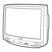
Identifies controls on the TV's front panel.
Explains the basic operations of the remote control.
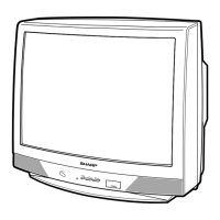
Identifies controls on the TV's front panel.
Explains the basic operations of the remote control.
Covers fuse protection, X-radiation circuit test, and high voltage checks.
Notes on using non-metallic tools and unit warm-up time.
Steps to access and leave the service menu.
Guides on choosing and modifying service adjustment numbers.
Adjustments for RF signal reception and screen picture settings.
Procedures for white balance, tint, and sub-color settings.
Adjustments for Picture-In-Picture display brightness.
Adjustments for picture focus, vertical size, and linearity.
Adjustments for horizontal position, EW parabola, trapezium, and corner.
Adjusts caption position and miscellaneous options.
Detailed steps for adjusting MTS audio levels and VCO.
Specific adjustments for PIP Y-level, Tint, Color, and offset.
Visual representation of component placement on the main board.
Visual representation of component placement on the main board.
Illustrates signal paths and module interconnections.
Illustrates signal paths and module interconnections.
Explains symbols, ratings, and conventions used in schematics.
Details conditions and methods for waveform analysis.
Information on safety-critical parts and replacement component selection.
Instructions on how to correctly order replacement parts.
Lists components designated as X-ray related for safety.
Lists the main PWB assemblies for both models.
Illustrates the steps and materials for packing the television.