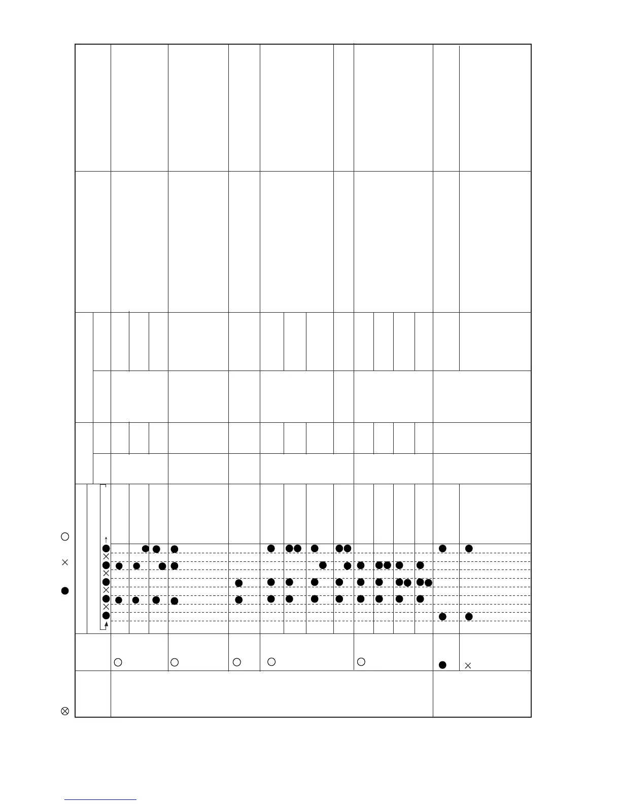
: Flashes in 2-sec intervals (normal) : On : Off : Flashes 3 times in 0.2-sec intervals
Status of
indoor/
outdoor units
Indication
by LED on
outdoor
unit
Indication by operation lamp on indoor unit
Content of diagnosis
Main category Sub-category
Inspection location/method Remedy
Lighting pattern at the time of timer lamp lighting
Off for 5 seconds
Main
category
Sub
category
Malfunction No.
*3: The content of diagnosis is transferred to the indoor unit via serial communication, but it does not trigger a complete shutdown operation. Number of repetition °: No complete shutdown
(1) Check the wires between units.
(2) Check voltage between Nos. 1 and 2 on
the indoor/outdoor unit terminal boards.
(1) Check the wires between units.
(2) Check the outdoor unit fuse.
(3) Check 15-V, 13-V and 5-V voltages on
the PWB.
Check resistance between IPM terminals.
(4)
Check pins No. 5 and 7 of connector CN3 of
the outdoor unit fan motor for short-circuit.
(5) Outdoor unit control PWB
(1) Connect stable power supply.
(2) Replace the outdoor unit control
PWB assembly.
(1) Correct the wiring.
(2) Replace the fuse or outdoor unit
control PWB assembly.
(3) Replace the outdoor unit control
PWB assembly.
(4) Replace the outdoor unit fan motor.
(5) Replace the outdoor unit control
PWB assembly.
Serial open circuit
Outdoor unit does
not turn on due to
erroneous wiring
Operation lamp
Cluster lamp
Operation lamp
Cluster lamp
Wires between
units
Indoor unit in
operation
Outdoor unit
in temporary
stop
Operation lamp
Cluster lamp
Operation lamp
Cluster lamp
Operation lamp
Cluster lamp
14 time
Indoor/
outdoor units
in complete
shutdown
14 0
13 0
-1
Operation lamp
Cluster lamp
-2
Operation lamp
Cluster lamp
-4
Operation lamp
Cluster lamp
-5
Operation lamp
Cluster lamp
-3
Operation lamp
Cluster lamp
-2
17 0
DC compressor
Compressor startup
error
(1) Check the colors (red,white,orange)of the comp-
ressor cords for proper connection. (PWB side,
compressor side)
(2)
Check if the IPM terminal resistance values are uniform.
(3)
Check if outdoor main relay (MRY1) turns on and
voltage of both end of the capacitor (C10) has
become DC330V.
(4)
No abnormality found in above inspections(1)and(3).
(5)
No abnormality found in above inspections(1)and(4)
.
(1) Correct the installation. (U:Red,V:White,
W:Orange)
(2)
Replace the outdoor unit control PWB assembly.
(3) Replace the outdoor unit control PWB
assembly.
(4)
Replace the outdoor unit control PWB assembly.
(5) Replace the compressor.
Compressor rotation
error.
(at 120º energizing)
Compressor rotation
error
(at 180º energizing)
Detection error of
inverter current.
Outdoor unit
PFC Module
PFC Module over
voltage error
(1) Check the connector of PFCM for secure
installation.
(2) Check the AC power supply voltage for
fluc
tuation.
(3)
No abnormality found in above inspec
tion (1).
(1) Correct the installation.
(2) Connect stable power supply.
(3) Replace tfe outdoor unit PFCM PWB
or control PCB assembl
y.
PFC Module PFCM
error
PFC Module clock
error
PFC Module filter
low valtage error
(1) Check the circuit of detection of inverter
current.
(1) Replace the outdoor unit control PCB
assembl
y.
13 time
(1) Check the connector CN3 of the outdoor
unit DC fan motor for secure installation.
(2) Check outdoor unit DC fan motor for
proper rotation.
(3) Check fuse FU3.
(4) Outdoor unit control PCB.
(1) Correct the installation.
(2) Replace the outdoor unit fan motor.
(3) Replace the outdoor unit control
PCB assembly.
(4) Replace the outdoor unit control
PCB assembly.
Outdoor unit DC fan
rotation error.
Operation lamp
Cluster lamp
Outdoor unit DC
fan
11 time
10 time
11 0
10 0
(1) Replace the outdoor unit control PCB
assembly.
EEPROM
error
1
Operation lamp
Cluster lamp
Operation lamp
Cluster lamp
Operation lamp
Cluster lamp
2
E
EPROM (outdoor)
d
ata error
EEPROM (outdoor)
data error
EEPROM (outdoor)
d
ata error
Operation lamp
Cluster lamp
12 0
Thermal
fuse
in terminal
b
oard
Thermal fuse error in
terminal board
(for power supply
)
(1)Ch
eck the thermal fus
e in termina
l
board
(
for Power s
u
pply)
(2)Ch
eck connector CN5
o
f the outdoor
u
nit.
(1) Replace terminal board for Power supply
(2)
Replace the outdoor unit control PCB assembly.
12 time