EasyManua.ls Logo

Sharp AE-XM24HR User Manual

Sharp AE-XM24HR
50 pages
To Next Page IconTo Next Page
Page #1 background imageLoading...
Page #1 background image
SERVICE MANUAL
Parts marked with " " are important for maintaining the safety of the set. Be sure to replace these parts with specified ones for maintaining the
safety and performance of the set.
This document has been published to be used for
after sales service only.
The contents are subject to change without notice.
CHAPTER 1. SPECIFICATION
[1] SPECIFICATION............................................ 1-1
[2] EXTERNAL DIMENSION............................... 1-2
[3] CAPACITY TABLE ......................................... 1-2
[4] ELECTRICAL PARTS .................................... 1-3
[5] WIRING DIAGRAMS...................................... 1-4
CHAPTER 2. EXPLANATION OF CIRCUIT AND OP-
ERATION
[1] BLOCK DIAGARM ......................................... 2-1
[2] FUNCTION..................................................... 2-2
CHAPTER 3. FUNCTION AND OPERATION OF PRO-
TECTIVE PROCEDURES
[1] PROTECTIVE FUNCTIONS AND OPERA-
TIONS ............................................................ 3-1
[2] TROUBLESHOOTING GUIDE....................... 3-3
CHAPTER 4. REFRIGERATION CYCLE
[1] REFRIGERATION SYCLE.............................4-1
[2] PERFORMANCE CURVES...........................4-3
CHAPTER 5. DISASSEMBLING PROCEDURE
[1] OUTDOOR UNIT...........................................5-1
Parts Guide
TopPage
MULTI SPLIT TYPE
ROOM AIR CONDITIONERS
MODELS
OUTDOOR UNIT
AE-XM24HR
In the interests of user-safety (Required by safety regulations in some
countries) the set should be restored to its original condition and only
parts identical to those specified should be used.
S6721AEXM24HRT
CONTENTS
Question and Answer IconNeed help?

Do you have a question about the Sharp AE-XM24HR and is the answer not in the manual?

Sharp AE-XM24HR Specifications

General IconGeneral
BrandSharp
ModelAE-XM24HR
CategoryAir Conditioner
LanguageEnglish

Summary

Chapter 1: Specification

[1] Specification

Detailed technical specifications of the unit, including electrical data and capacities.

[2] External Dimension

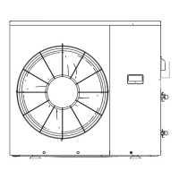
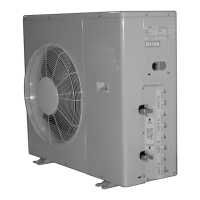
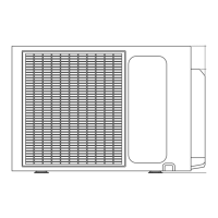
Physical dimensions and layout of the outdoor unit.

[3] Capacity Table

Combinations of indoor units and their cooling/heating capacities.

[4] Electrical Parts

List of electrical components and their part codes.

[5] Wiring Diagrams

Electrical wiring schematics for the unit.

Chapter 2: Circuit and Operation Explanation

[1] Block Diagram

High-level overview of the unit's functional blocks.

[2] Function

Detailed explanation of the unit's operational functions and controls.

Chapter 3: Protective Procedures

[1] Protective Functions and Operations

Overview of safety and protective mechanisms and their operation.

[2] Troubleshooting Guide

Procedures for diagnosing and resolving common faults.

Chapter 4: Refrigeration Cycle

[1] Refrigeration Cycle

Diagram illustrating the refrigerant flow and key components.

[2] Performance Curves

Graphs showing performance characteristics under various operating conditions.

Chapter 5: Disassembling Procedure

[1] Outdoor Unit

Step-by-step instructions for disassembling the outdoor unit.

Parts Guide

[1] Control Box Parts

List of components for the control box assembly.

[2] Cabinet and Parts

List of cabinet and chassis components.

[3] Cycle Parts

List of parts related to the refrigeration cycle.

[4] Other Parts

Miscellaneous parts not categorized elsewhere.

[5] Packing Parts

Components included in the product packaging.

[6] Accessory Parts

Optional or supplementary parts for the unit.

Related product manuals