0
-0
1
-0
5
-0
6
-0
7
-0
8
-0
11 -0
2
-0
-1
-2
-3
-1
-2
-3
-1
-2
-5
-4
-1
-2
-3
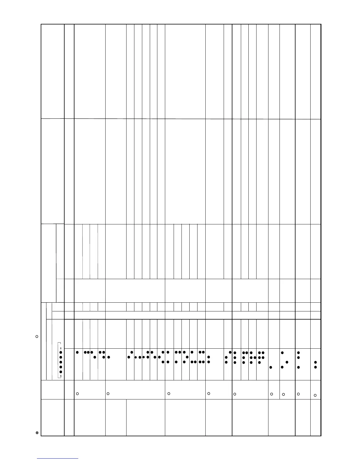
Status of
ind
oor/outdoor
u
ni
t
s
Indi
ca
ti
on by
LED1 on
o
utdoor unit
*2
I
ndication on indoor unit
C
o
ntentofdi
a
gnos
is
In
spection location
/method
Remedy
Flo
or / ceil
ing
Wall
(
P
anel)
Li
ghti
ng pat
ter
n at the time of timer
l
amp lighti
ng
M
ain
Sub
fo
r
5
seconds
Mai
ncateg
or
y
S
u
b
cat
e
g
ory
I
ndoor
/o
utdoor units in
operati
on
Norm
al
flashing
N
ormal
_
_
_
_
_
Indoor/outdoor uni
ts
in complete shutdow
n
1ti
m
e
Oper
ati
on lamp(RED)
C
luste
r
lam
p(
B
LUE)
Oper
ati
o
n
l
am
p
(
RED)
Clu
ster l
a
mp(BLUE)
Oper
ati
on lamp(RED)
Cluster lamp
(
BL
U
E)
Oper
ation lamp(RED)
Cluster lamp
(
BLUE)
O
pe
ratio
n
l
am
p
(
RED)
C
luste
r
lam
p(
B
LUE)
Oper
ation lamp(RED)
C
luste
r
lam
p(
B
LUE)
Oper
ati
on lamp(RE
D
)
C
luste
r
lam
p(
B
LUE)
O
p
eratio
n
l
am
p
(
RED)
Cluster lamp(BLUE)
O
p
eratio
n
l
am
p
(
RED)
C
luste
r
lam
p(BLUE)
Oper
ati
on lamp(RE
D
)
C
luste
r
lam
p(
B
LUE)
Oper
ati
on lamp(RED)
Clu
ster lamp(BL
U
E
)
Oper
ati
o
nl
a
mp(RED)
Clu
ster lamp(BLU
E
)
O
per
ati
o
nl
a
m
p
(RED)
Clu
s
ter lamp(BLU
E
)
Oper
ati
o
nl
a
mp(R
ED
)
Clu
ster l
amp(BL
U
E
)
Opera
ti
o
nl
a
mp(R
ED
)
Clu
ster l
amp(BL
U
E
)
O
perati
o
nlam
p(
RED)
Clu
s
ter lamp(BLU
E
)
Oper
ati
on lamp(RED)
Clu
ster lamp(BLU
E
)
Oper
ation l
a
mp(RED)
Clu
ster lamp(BLU
E
)
Opera
ti
o
nl
a
mp(R
ED
)
Clu
ster l
am
p(BL
U
E
)
O
p
e
r
ationlam
p
(RED)
Clu
s
t
e
rlam
p(BL
U
E
)
Oper
ati
o
nlamp(R
ED
)
Clu
ster l
amp(BL
U
E
)
Ou
tdoor
u
nit
t
hermistor
shor
t
-
circuit
(
1)Measur
e
r
e
sista
nce of the outdoor unit thermistors.
(TH2
~
4
,6~8:Approx.4.4k at 25ºC
(2)Chec
kt
he leadwi
re of the outdoor unit thermistor for torn s
heath and
shortcircuit.
(
3)No
abnor
m
ality foundinabove i
n
s
pect
ions (1)
a
nd (2).
(1)Repl
a
c
e
th
eoutdoor unit thermistor
a
s
sembly.
(
2)Replace theoutdoor unit thermi
stor a
s
sembly.
(
3
)
R
e
place the outdoor
u
nit control PCB a
s
sembly.
Indoor/outdoor uni
t
si
n
compl
e
te shu
tdown
2time
Cycle
te
mperature
(1)Che
c
kth
eoutdoor unit air outlet for blockage.
(2)Ch
eck i
f
t
h
epow
e
r
sup
ply voltage is A
C
230V at full pow
er.
(3)Check the pi
p
econnections fo
r
refrigerant leaks.
(4)Mea
s
u
re r
esista
nc
e
of the outdoor unit compressor thermistor.
(TH1:Appr
ox.
53k at 25ºC)
(
5)Check the expansi
o
n valve for pr
o
per operati
o
n.
(
1
)
En
sure unobstructed ai
r flow from t
he outdoor unit air outlet.
(2)
C
onnect pow
e
r
su
pply of pr
oper voltage.
(3)Char
ge the s
p
ecifi
e
damountofrefrigeran
t
.
(
4)
Re
pl
a
ce the outdoor uni
t
compressor ther
m
i
sto
r
a
s
sembly.
(5)Repl
a
c
e the expan
si
o
n valve coil,expansi
on valve or o
utdoor unit
contr
ol PCB assembly.
Indoor uni
tin
operation
Out
door uni
t
i
n
temporar
y
sto
p
(Te
mporarystopfor cyclepr
ot
ection)
(Te
mpor
a
r
ystopfor cycle
pr
o
tection)
(
Tem
porary stop for cy
cle protec
t
ion)
IPM
h
i
g
htemper
a
tur
e
error
(1)Mea
sur
e
r
e
s
i
s
ta
nce of the heat-
sink th
er
m
i
sto
r
(CN8B).
(1)Change the heat-sink thermis
to
r
.
Indoor/outdoor units in
completeshutdown
5time
Ou
tdoor
u
nit
t
hermistor open-
ci
r
cu
it
(
1)Check connector C
N8A
andCN8Cofthe
outdoor
u
nit ther
m
i
sto
r
f
or
se
c
ure
i
n
stall
a
tion.
(2)M
easure resistance of outdoor
t
hermistors T
H1 ~ 4, 6 ~8.
(
3
)
Check
the leadw
ires of
thermistors T
H1 ~ 4,
6~8onthe outdoor u
ni
t
c
o
ntrol PC
B
for o
pen-
circuit.
(4)No
abn
orm
ality found in a
bove i
nspections (
1
)
th
r
o
ugh(
3
)
.
(
1
)
Correct
the instal
latio
n.
(2)Repla
ce
the outd
o
or unit thermistor assembly
.
(3)Re
pl
a
ce the outdoor uni
t
ther
mistor assembly.
(4)Rep
l
a
ce theoutdoor
u
nit contr
ol PCB
as
se
mbly.
In
door
/
outdoorun
its in
co
m
ple
te shutdow
n
6
time
Ou
tdoor unit
DC C
u
r
re
nt
D
C overcurrent erro
r
(1)IPM cont
i
nuity chec
k.
(2)Check the
IPM and heat si
n
kfo
rse
cure in
sta
lla
tion.
(3)Che
c
kt
h
e
outdooru
nit
fan moto
rfo
rprope
r
r
o
tation.
(
4
)
No abnormal
ity f
o
undinabove i
n
spectio
ns (
1)throu
gh (
3
)
.
(
5
)
No abnormalit
y
f
o
u
nd i
n
abo
ve
i
n
spect
i
o
ns
(1)th
r
o
ugh (
4
)
.
(1)Re
plac
e
the outdoor uni
t
IPM P
CB a
ssembl
y.
(2)Corre
ct the insta
l
l
a
t
i
on (
tigh
te
n
t
h
e screws)
.
A
pply silic
on grea
se.
(3)Repla
ce theoutdoor unit fan motor.
(
4
)
Re
p
l
a
ce t
he ou
t
door
u
nit I
P
MPCBass
e
mbl
y.
(
5
)
R
eplace
the co
m
pressor.
In
door
/outdooruni
t
s
in
co
mpl
e
te shutdow
n
7
time
Ou
td
oorunit
AC
Curre
nt
AC o
v
e
rcu
r
r
enter
ror
(1)
Ens
u
r
e
unobstr
u
c
t
ed air flow f
rom the
ou
td
o
or uni
t
air o
u
tlet.
(2)Che
ck t
he outd
oor unit f
an motor.
(1)En
su
r
e
unobs
t
r
u
c
t
ed air fl
ow from the
o
u
tdoor uni
t
a
ir ou
tlet.
(2)Check the ou
t
doorunitf
a
n
motor.
AC current error wh
e
n
O
FF
(1)IPM continuity c
h
eck
(1)R
e
place the o
u
t
d
o
or IPM P
W
B
AC maximumcu
rr
e
nt er
r
or
(1)En
su
r
e
unobstr
u
c
t
ed air fl
ow from the
o
u
tdoor uni
t
a
ir ou
tlet.
(2)C
heck the ou
t
doorunitf
a
n
motor.
(1)En
su
r
e
unob
st
r
u
c
t
ed air
f
l
ow from th
e
outdoor uni
t
a
ir ou
tlet.
(2)Check t
he outdoorunit
f
an motor.
AC curren
tdeficie
ncy er
r
or
(1)Re
pl
ace the outd
o
or uni
t
con
tr
o
lPCBa
s
sembl
y.
(2)Charge the spe
c
i
f
i
e
damount
of r
e
frig
eran
t
.
(3)Corre
ct refrig
eran
t clog
s. (
S
t
o
p valve
,p
ipe
,expansio
n
v
alve)
(1)Re
p
lace
the outd
o
or uni
t
co
n
t
r
o
lPCBa
s
s
e
mbl
y.
(2)Charge the sp
e
ci
f
i
e
damou
n
tofr
e
frig
era
nt
.
(3)
Corr
ec
trefrigerant clog
s
.(Stop valve,pi
pe,ex
p
ans
i
on v
a
l
v
e
)
In
do
o
r
/
outdoor
units in
complete shutdown
Ab
normal wi
re
che
ck
Abnormal wire check er
ror
(
1)Ch
eck theexpansion
v
a
lve. (un
i
t
A-
C)
(2)Are fo
ur e
xp
ansi
o
n val
ve
scon
nec
t
ed bym
i
sta
k
e
(3)Che
c
k
th
e
w
iring
betw
e
en units.
(1)Re
place t
he outdoor c
ontr
o
lbo
ard as
se
mbly
.
(2)Reat
ta
ch
(3)Che
c
kthew
iring bet
w
e
en units.
In
d
oor
/
outdoor
units in
c
o
mplete shutdown
Ou
td
oor unit
DC F
a
n
Ou
tdoorun
it
D
Cfa
n
rotat
i
on erro
r
(1)Chec
kconnec
to
rCN3 ofthe
o
utdoor un
it D
Cfanmotor for secure instal
lation.
(2)Checkt
he outdoor unit fan moto
rfo
r
p
r
o
per r
ot
ation.
(3)Check
fuse F
U
S
E
5.
(
4
)
Out
d
o
or uni
t
co
n
tr
o
lPCB
(1)Co
r
re
ct
the insta
l
lati
o
n.
(2)Rep
lace
th
eoutdoor un
it fa
nmoto
r
.
(
3)Re
p
l
a
ce theoutdoor unit contr
ol PCB a
s
se
mbly.
(
4
)
R
epl
a
ce t
he o
ut
door
u
nit c
o
ntrol P
C
B
as
sembly.
Flashes in
1-
se
ci
n
ter
va
l
s(normal)
:
1sec ON / 1sec OFF
X : :
OF
F
:
Flashe
s3timesi
n
0.2-sec inter
vals
8
time
11 time
X
Heat e
xc
h
angerthermi
st
or short cir
cu
i
t
erro
r
Ou
tdoor tem
p
er
a
tur
ethermistor
sh
ort
circuit
error
S
uc
t
ion ther
m
istor s
hort circuit err
o
r
The
r
m
i
stor Unit A - C the
r
mistor
sho
r
t
c
ircu
i
t
error
C
ompressor high temperature error
Tempor
ary stop due t
o
c
omp
ress
or
d
i
scha
rge overheat.
Tem
porary st
op due to indoor uni
t
h
eat exchanger overheat.
Heat ex
ch
anger thermis
t
or open
circuit e
r
ror
Outdoor temperature thermistor open
circuit error
S
u
ct
ion ther
m
is
t
or
o
pen ci
rcuit erro
r
Su
cti
on thermi
st
or o
p
en c
ircuiter
ror
Disch
ar
ge ther
m
isto
rop
en ci
rcu
it
erro
r
T
h
er
m
is
t
or U
n
it A - C the
r
m
i
st
or open
c
ircu
it error
Tempor
a
r
y stop due to out door unit
heat exchanger overh
e
at.
Oper
ati
on l
a
mp(RED)
C
l
u
ster lam
p(
BL
U
E
)
-1
IPM p
i
n
le
vel e
r
ror
(1)Ch
ec
kth
eIPM is
a
ttached co
rrecity to
the
outdoor uni
tI
P
MPW
B.
(1)Re
place t
he outdoor u
n
i
t
IPM PWB ass
e
mbly
.
In
do
o
r
/
outdoor
units in
c
o
mplete shutdown
12 t
ime
Oper
ation l
a
mp(RED)
Cluste
r
l
a
mp(BLU
E
)
12
-0
The
r
m
al fuse
in
te
rmina
lbo
ard
The
r
m
al fuse er
r
or in t
erminal boar
d
(for power sup
ply
)
(
1)Ch
eck thethermal fuse i
n
terminal boar
d
(for Po
w
er s
u
ppl
y)
(2)C
heck connector CN5 of theoutdo
or unit.
(1)Re
place t
erm
i
n
al board for Powe
r
su
p
ply
(2)Replace
t
h
eoutdoor u
n
it con
trol P
CB a
ssembl
y.
9
time
Oper
ati
o
nlamp(RED)
Clu
ster la
m
p(BL
U
E
)
-4
4
w
a
y valve er
ror
o
r
G
as leake
rro
r
(1)Ch
eck to make sur
e
o
u
tdoor uni
t
t
her
m
istor TH2 (exch
ange) andTH3(
p
i
p
e
te
mper
at
ur
e
)arein
sta
lle
dinc
orre
ct por
ti
o
ns.
(2)Che
c
ki
f
the refig
e
r
a
nt volume i
sabnomally low.
(
3
)
Check the 4-way v
a
l
ve
for p
r
oper operati
o
n
.
(1)Co
r
rect
the i
nstal
lat
i
o
n.
(2)Cha
nge t
he spe
ccifi
e
damount o
f
r
e
fr
ig
erant.
(
3
)
Rep
l
a
c
ethe 4-wa
yv
alve.
9
Cycl
e
te
m
p
eratur
e
-5
-4
T
e
mper
at
ure stop due to IPM
over h
eat.
Oper
ation lamp(RED)
Cluster lamp(BLUE)
 Loading...