AEX2M14LR
5 – 3
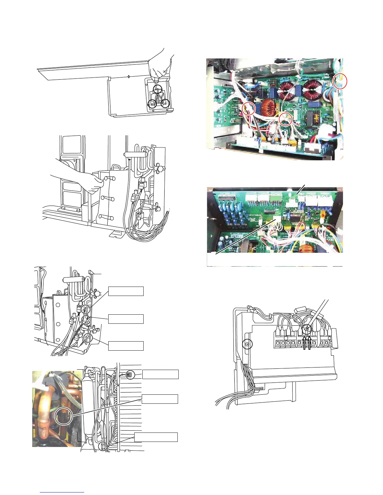
13.Remove the 3 screws fixing the coil for PFC then remove it
NOTE: When the coil re-install, silicone grease must be paste to the
back face of the coil.
14.Remove the 3 strings on the compressor cover A then remove it
15.Remove the 6 thermistors on copper tube.
NOTE: Caution to position when re-installing.
Refer to page 5-5 (Mounting position of thermistors and expansion
valves)
How to disassemble the control box assembly
16.Cut the 3 wire fixing bands.
Disconnect the 7 connectors. [CN6, CN15, CN9A, CN16, CN17,
CN5, CN101 (IPM)]
Lift up the Control Board Unit (PWB) and remove it.
17.Disconnect the 2 terminals (Blue and Brown).
And Remove the 3 screws fixing the terminal board angle assembly
then turn it inside out.
TH8 (BROWN)
(Just on the tilted pipe)
(Just on the horizontal pipe)
(Just on the horizontal pipe)
TH7 (WHITE)
TH6 (BLUE)