AEX2M14LR
5 – 5
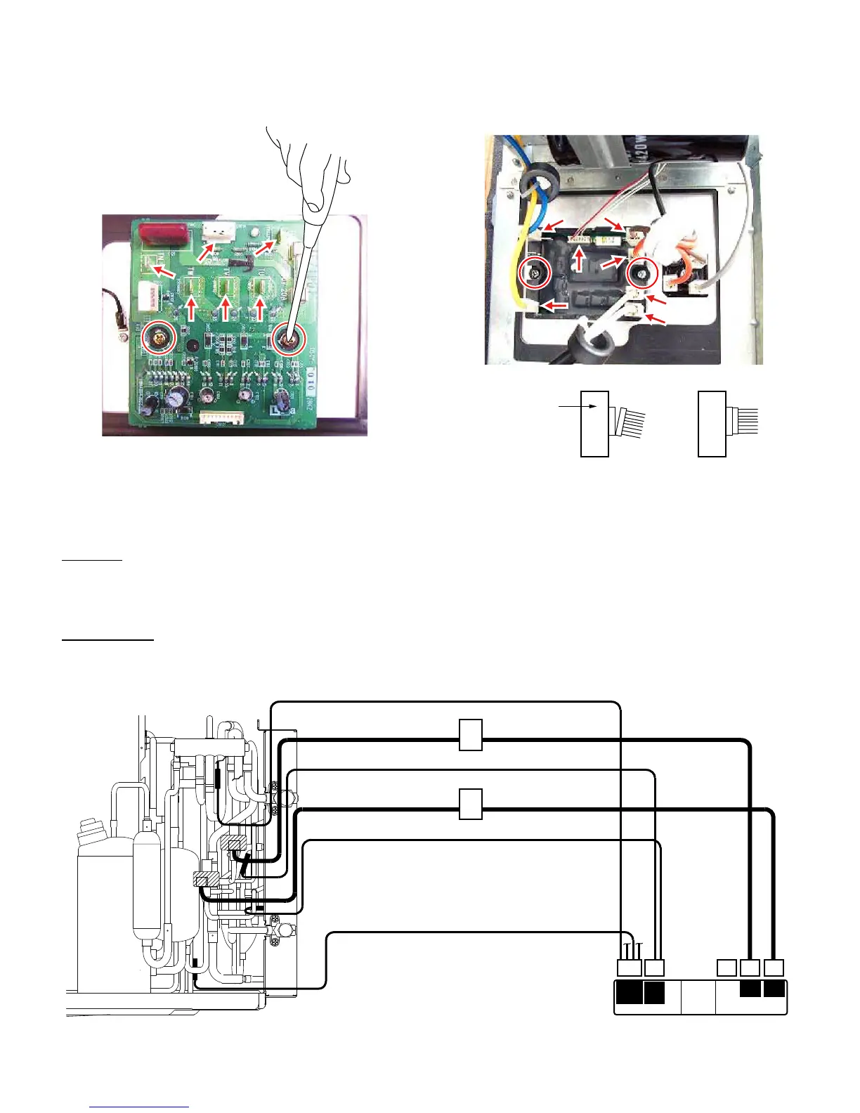
24.Disconnect the 5 terminals (TP, TU, TV. TW, TN) and 1 connector
(CN114) on the IPM PWB. And Remove the 2 screws fixing the
IPM PWB and remove it.
NOTE: When the IPM PWB re-install, silicone grease must be paste
to the back face of the IPM.
25.Disconnect the 6 terminals (P, Io, +, -, L1, L2) and 1 connector
(CN13) on the active filter. And Remove the 2 screws fixing the
power module and remove it.
NOTE: When the active filter re-install, silicone grease must be paste
to the back face of the Active Filter.
CAUTION: Fix the connector of the power module securely.
2. Mounting position of thermistors and expansion valves
Mounting position of thermistors and expansion valves are shown below.
Thermistor
• Check the cord color of thermistor before mounting.
• Thermistor Suction, Suction A, Suction B, Suction C are mounted on GAS side pipes.
• Thermistor Heat exchanger is mounted on LIQUID side pipe.
Expansion valve
• Check the labels before connecting to the Control Board Unit.
CAUTION: Mismounting and misconnecting will cause error or failure.
Thermistor Suction A (Blue)
Thermistor Suction (Black)
Thermistor Suction B (White)
Label
Connector label
Expansion valve B
Label
Expansion valve A
B A
Expansion valve
Thermistor
Heat
exchanger
Compressor
Suction B
Suction C
Suction A
Suction
Outdoor temp.
Thermistor Heat exchanger (Orange)