7
AH-X08BE/10BE/13BE
AY-X08BE/10BE/13BE
AY-X08BE-C/10BE-C
AU-X08BE/10BE/13BE
AE-X08BE/10BE/13BE
AE-X08BE-C/10BE-C
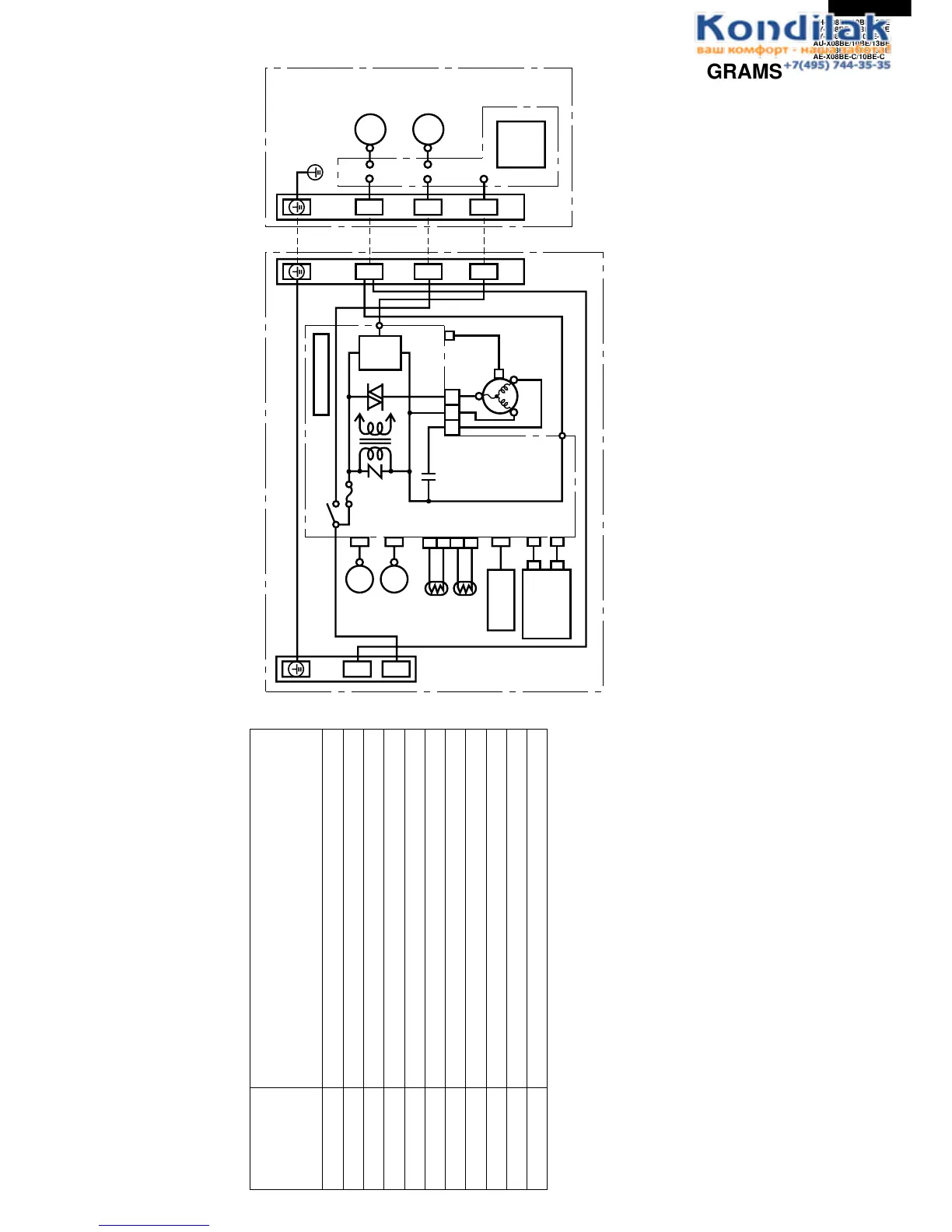
Figure W-1. Wiring Diagram for AH-X08BE/X10BE/X13BE and AY-X08BE/X08BE-C/X10BE/X10BE-C/X13BE
WIRING DIAGRAMS
TERMINAL BOARD 1
GREEN-YELLOW
POWER
SUPPLY
SINGLE
PHASE
INDOOR UNIT
OUTDOOR UNIT
BROWN In Out
C1
RY1
WPE1
250V
3A
CONTROL BOARD UNIT
LOUVER
(UPPER)
LOUVER
(LOWER)
ROOM TEMP.
THERMISTOR
PIPE TEMP.
THERMISTOR
TH1
TH2
3
4
1
2
CN3
YELLOW
ORANGE
RECEIVER
BOARD UNIT
DISPLAY
BOARD
UNIT
BCN2
BCN3
CN101
CN102
CN2
CN7
BCN1
TRANS1
SSR1
S
SERIAL
SIGNAL
CIRCUIT
FAN MOTOR
CAPACITOR
430V 2µF
CN6
CN1
TERMINAL BOARD 2
TERMINAL BOARD
BLACK
RED
BLUE
BLUE
5
3
1
N
BLACK
FAN MOTOR
BLUE
RED
COMPRESSOR
FAN MOTOR
UNIT
TO
UNIT
CORD
CONTROL
BOARD
UNIT
N
1
11
NN
22
R.P.M.
SIGNAL
INTERNAL
THERMAL
FUSE
LED INDICATION FOR SELF-DIAGNOSIS
Abnormal contents
Temperature
Indicator
Blinking No.
1
2
3
4
5
6
7
14
17
18
19
Short circuit of the outdoor thermistor
Overheat of the compressor
Abnormal AC current
Compressor lock
Open circuit of the outdoor thermistor
AC overcurrent
Power module
(
IPM
)
abnormality
Open circuit of serial signal line
Short circuit of serial signal line
Abnormal fan motor of indoor unit
Abnormal power factor module
(
AFM
)
Indication of the abnormal condition >
LED indicator will blink, if the set
is in abnormal condition.
M
M
M
M