AYXPC18LR
1 – 5
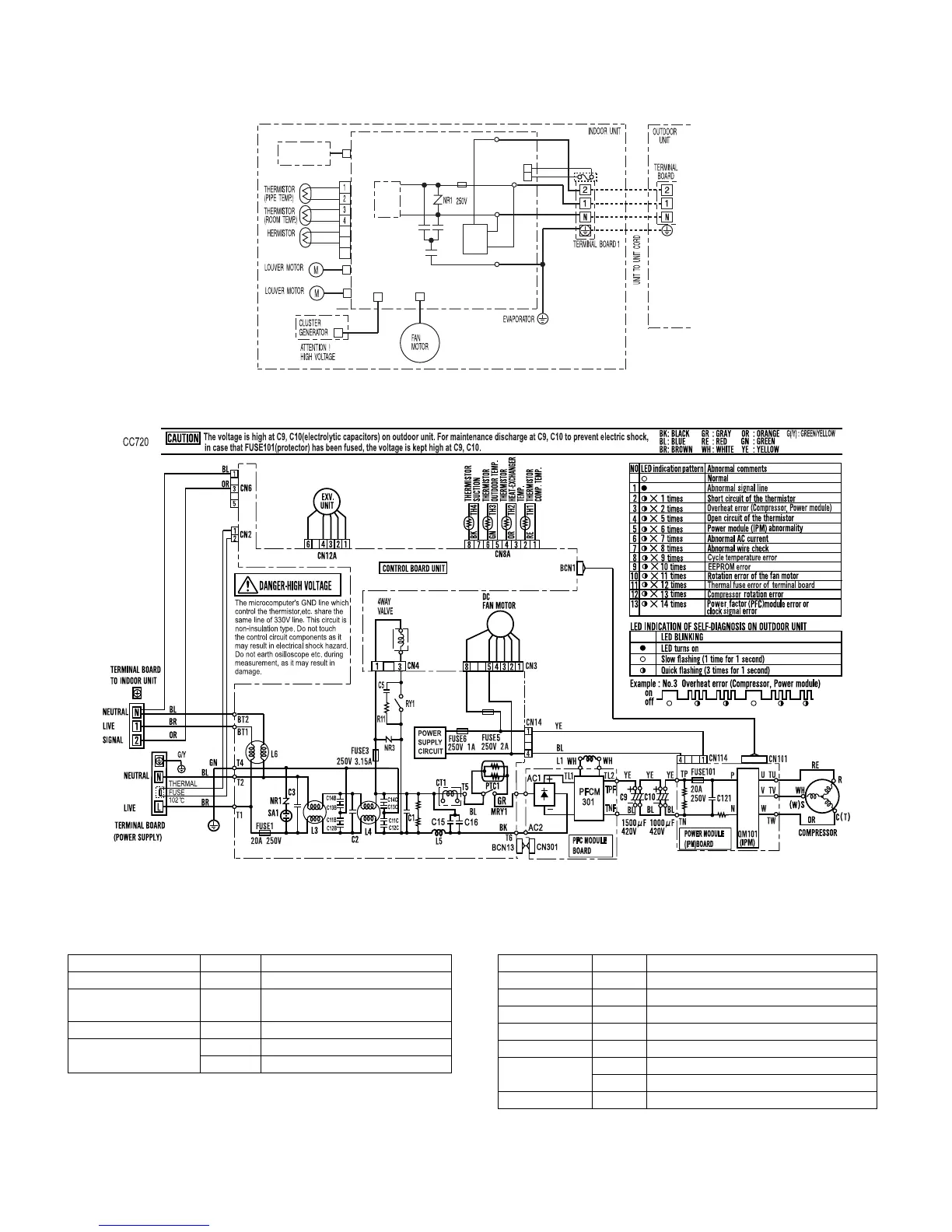
[3] WIRING DIAGRAMS
1. Indoor unit
2. Outdoor unit
[4] ELECTRICAL PARTS
1. Indoor unit 2. Outdoor unit
CN7
CN㧢
CN4
(HORIZONTAL)
CN2
(E)
(N)
crN
OKR^
THERMAL
FUSE
CN10
POWER
SUPPLY
CIRCUIT
`QV
`QT
`QU
MAIN CONTROL BOARD UNIT
ORANGE
YELLOW
6
5
7
BLACK
(VALVE TEMP.)
(VERTICAL)
CN3
(S)
RED
BROWN
BLUE
GREEN-
YELLOW
CONTROL
BOX
(L)
SUB CONTROL
BOARD UNIT
CN8
SERIAL
SIGNAL
CIRCUIT
Part Name Items Specifications
Terminal Board Rating 300V 25A
Printed Wiring Board Material Paper Base Phenolic Resin
(UL94V-0)
Fan motor Type MLB438,DC Motor
Louver Motor Rating DC12V
Type MP24GA
Part Name Items Specifications
Fuse1 Rating 250V, 20A
Fuse101 Rating 250V, 20A
Fuse3 Rating 250V, 3.15A
Fuse5 Rating 250V, 2A
Fuse6 Rating 250V,1 A
Compessor Rating DC Brush-less
Type Motor 1000W
Fan motor Type MLB078, DC Motor